 Didn't you say the controls had no effect?
Does the oscillation continue on the pre with the master down?
If yes, can you find them on some preamp supply rail?
If so there may be in fact a problem with the supply.
If some stage is oscillating by itself, i.e. without feedback via the supply rails, the reason way even be some bad wiring layout.
Sorry, I was not specific enough
Does the oscillation continue on the pre with the master down?
If yes, can you find them on some preamp supply rail?
If so there may be in fact a problem with the supply.
If some stage is oscillating by itself, i.e. without feedback via the supply rails, the reason way even be some bad wiring layout.
I removed V1 and V2, and the oscillation still there. If I remove V3 or V4 it dissapears.
Then, I decided to leave all the tubes and start to remove the plate voltage. So, if I also removed the power for V3 at R31, the oscillation still there. Same case if I remove the power for V4 at R33.
Another thing about V4, only half tube is used. The other half is no connected, but the fillament at PIN 5 is connected.
The unused electrodes of V4 are tied to GND?
Did I get that right? When pulling either V3 or V4 oscillation stops, but as long as they are installed, you would have to remove plate voltage on both V3 and V4 to stop it? It still is not clear to me whether the oscillation depends on the master volume setting. Is it gone when turned down or just not audible any more? Have you measured at the output of V4?
Did I get that right? When pulling either V3 or V4 oscillation stops, but as long as they are installed, you would have to remove plate voltage on both V3 and V4 to stop it? It still is not clear to me whether the oscillation depends on the master volume setting. Is it gone when turned down or just not audible any more? Have you measured at the output of V4?
The unused electrodes of V4 are tied to GND?
Yes, the electrodes are grounded
Did I get that right? When pulling either V3 or V4 oscillation stops, but as long as they are installed, you would have to remove plate voltage on both V3 and V4 to stop it ?
So, if I remove the tubes V3/V4 and if I remove the plate voltage, the oscillation still present
It still is not clear to me whether the oscillation depends on the master volume setting. Is it gone when turned down or just not audible any more?
Have you measured at the output of V4?
Yes, the oscillation depends on the master volume. So, as soon as I put the master on zero, the oscillation is gone.
I measure with the scope before V3, and I couldn't see any oscillation. However, when I measure on PIN1 of the Master Pot I see some noise in the scope. I am not sure if that is the PLUK noise, because I hear it every 3/4 seconds
Attachments
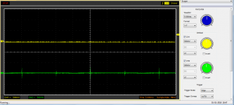
The timebase of the scope is set to 5ms? Then this can't be spikes occurring every 3 or 4 seconds. You should be able to see the "your" oscillation on the speaker output. You will probably find it on the grids of the power tubes as well. Do you see it on any point of the HV supply? Going backwards from the speaker, look for any signs of your noise on the signal path. You should to find out if it caused by interference over the supply.
I am still not sure if you get it from the pre or power stage...
You say it is still present with V3&4 removed?? This would point to the power stage, but it does not make sense that something should change with the master vol position then.
I am still not sure if you get it from the pre or power stage...
You say it is still present with V3&4 removed?? This would point to the power stage, but it does not make sense that something should change with the master vol position then.
Last edited:
I made a small video (Shared album - Gustavo Rangel - Google Photos), so you can hear better how it sounds. The volume of the pluk is a bit low, so I hope you can hear it.
I let the amplifier on for a while, and the pluk-pluk disappear by itself. Then it comes again. Then it goes again. It's like it comes always around 10min after I switch ON the amp, stays for 10min and then it goes
I will measure the signal from the grid at the KT88, and let you know how it looks like
Thank a lot for your help, it is very valuable for me
However, when I measure on PIN1 of the Master Pot I see some noise in the scope. I am not sure if that is the PLUK noise, because I hear it every 3/4 seconds
Sorry, that was some misunderstanding of mine, I thought of one in 3 seconds, you meant 3 times a second. Not that important.
Was the control up or down?
I would proceed like that:
As the spikes on your scope cannot be your noise (what you measured is probably line related, 200 Hz) see what the speaker output looks like. Set your scope to about 250ms/div, if possible. Or choose another convenient setting where it can be clearly displayed. Then trace the signal back.
In similar cases, I switch the input of my scope to AC-coupling and look for every sign of this signal, also on the supply rails. But I don't know if this is possible with your PC device? And if so, make sure the coupling withstands the HV and use a 10:1 probe for the supply.
Shorten the input (or the grid R, respectively) of V4a, V5a. Does it go away?
Pull one pair of power tubes, then the other. Changes?
Do you feel the master volume just controls the level of this signal as if it would be coming from the pre?
Or is there a point of potentiometer setting where the oscillation rather stops?
You leave the amp on for a while and it comes and goes? Low freq instability could come from the power supply as well. Can you measure the voltages on the anode and g2 supplies for the KT88s? Both dc and the ac ripple. Are these readings different when the amp is oscillating and when it is silent?
Low volume, low freq can still be high voltage swings and ditto currents. I once had an amp that had a low freq oscillation when the volume was higher than zero. It turned out that there was not enough decoupling between the anode and g2 supply of the power valves:a 150 ohm choke and similar capacity before and after it. The result was that any sag on the anode supply caused a reverse current: the electrolytic for g2 was charging the electrolytic for the anodes. A simple diode blocking this reverse current fixed it. Now in your amp, there is only 470 ohms between anode and g2 supply and similar capacitance around it. Could be a similar problem. Put a diode in series with this 470 ohm resistor to try this out.
Besides all this, there are a few suggestions I'd like to make. A 3A slow blow fuse for the HT is dangerous. If something goes catastrophically wrong on the HT side, you want it to blow fast and with less margin. I know the GEC datasheet lists the max g1 grid leak for fixed bias at 100k, but I'd prefer lower values, specially for new production. The similar 6550(a) has a 50k max. In your amp you have 100k+22k. You have 100uF as the first reservoir cap, which is directly feeding 4 KT88s (200 in series with 200). This is not much considering KT88s can draw a lot of current. Lasty, 600+ Volts and 200W from a quad of KT88s is a heavy task for any KT88. Both for NOS and new production. I wouldn't expect long life.
You're absolutely right, I did not have a close enough look at the power supply.
Another thing: The bias voltage has a poor filtering. In this circuit, I would include another filter cap after the 22k resistor. This also would elimininate a rest of signal crosstalk between the two signal lines to the power tubes. Don't make it too large to ensure fast build-up of bias voltage.
But I would prefer a different layout of the bias circuit anyway, this circuit may destroy the power tubes if one of the trimmers fails. I would wire the trim pots as the lower resistors of voltage dividers, so failure would result in bias going down instead. Consider that this prohibts the use of a common filter resistor for both trimmers. I would even wire the 2nd caps directly to both outputs of the bias circuits then.
Last edited:
Sorry, that was some misunderstanding of mine, I thought of one in 3 seconds, you meant 3 times a second. Not that important.<snip>
I changed the value of the tail resistor of the LTP from 220k to 22k. It was way too large. Now the amplifier is loud as expected and also the pluk/pluk seems to go away.
Now I just need to make the PRESENCE work. I tried different circuits, but so far no luck.
I changed the value of the tail resistor of the LTP from 220k to 22k. It was way too large.
Sometimes it can be that easy...
I missed that resistor completely. That's the problem with the iPad... It wasn't 220k on your first schematic, why did you change it at all? You could change the presence control to FB-based Marshall-like design?
Did you think about the bias supply? I would at least add emergency resistors to the trimmers and filter caps from each wiper to GND. Not much effort.
You could change the presence control to FB-based Marshall-like design?
I will do that. Now that I solved almost all the problems that I got, there is a new coming out. When I put all the pot at 10 I get a lot of noise. If I move the Master back to 8, the noise goes again. I cleaned the pot just in case there was some dust inside. It is better, but still not perfect.
Do you have any suggestion for that?
When I put all the pot at 10 I get a lot of noise. If I move the Master back to 8, the noise goes again. I cleaned the pot just in case there was some dust inside. It is better, but still not perfect.
Cleaning a pot is unlikely to change its noise at the end points. That cannot be the reason. First, would it make sense to operate an amp with all controls to 10? It could be necessary to fine- tune the control ranges of your pots and maybe then gain structure. The amp must have lots of gain, two inputs, and a band pass filter, so you certainly can expect a certain amount of noise. What does the noise look like on the scope? Maybe some RF oscillation occurs at high settings and the noise you hear is just the audible portion of this.
Issues Hybrid Hiwatt/Ampeg
Hi,
Few months ago I did an amplifier based on a Hiwatt/Ampeg. I had several issues which I listed here.
http://www.diyaudio.com/forums/inst...31-clone-hybrid-hiwatt-ampeg.html#post5275003
All the issues were solved. However, recently I found another couple of problem
1.- When all the knobs are at 0 and mid-range is putted at 10, as soon as I start to increment the Bass I start to hear POC POC POC very fast and a bit strong
2.- Sometimes, for some annoying reason, I start to hear a POC POC POC when I play with the Bass. This is not systematic, it happens sometimes. I thought it was related with motorboarding. I changed the configuration of the power supply few times, but so far no luck.
Can anyone give me some hints about it?
Attachments
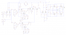
I would be trying 2K2 grid stop resistors on the grids of V2a and V2b. Higher gm tubes like the12AU7 are susceptible to parasitic oscillation which can manifest itself as that POC POC POC. With the MID control at 10 you have max signal which would aggravate this.
This happens a lot in HIFi preamps with high gm twin triodes like the 6DJ8.
If that doesn't fix it I would then go on to add 10K grid stops to V3a and V3b. Cheers, Ian
This happens a lot in HIFi preamps with high gm twin triodes like the 6DJ8.
If that doesn't fix it I would then go on to add 10K grid stops to V3a and V3b. Cheers, Ian
Last edited:
Hi,
Thank for the feedback. I added both grid stoppers on V2 and V3. It improves the behavior on the midrange issue, but the POC POC POC still there. The difference is that it is happening only on one channel and at a higher level on the BASS
The random POC POC POC, so far is not happening. It is difficult to reproduce it
Because you are seeng the problem on just one channel now would normally point at the front end 12AX7 but I still suspect the 12AU7 phase splitters which do the mid function.
They (split load phase splitter wired or cathode follower wired 12AU7) are susceptible to capacitive loads on the cathode so next trick in eliminating 12AU7 parasitic oscillation is to use "build out" resistors on the feeds from the 12AU7 cathodes to C14 and C16. That "moves" the phase shift away from the cathode to the other side of the "build out" resistor.
Remembering that the tube drive signal is the voltage from grid to cathode, so if you decrease phase shift of the cathode signal voltage, you decrease the grid to cathode input signal phase shift, and your triode is more stable.
The output impedance from the 12AU7 cathodes is going to be really low, approaching 1/gm, say some thing like 100 Ohms, so try a 220 Ohm series "build out" resistor in series with the feed to C14, C16. Not 100% sure of that 100 Ohms output impedance "butt pluck / err. educated estimate from insufficient data" - so try resistors up to not more than 1K5. If that doesn't fix, higher values wont either.
That and the grid stops you have already fitted should "bomb proof" the 12AU7 stage.
If that doesn't fix it then you can reasonably safely conclude that stage is not at fault and look elsewhere. Probably back to the input stage.
Teaching Grandma to suck eggs BUT Have you gone over the power rail bypass caps. A dodgy joint at either end of a single bypass cap could also cause that POC POC POC from the "motor boating" form of oscillation via feedback on the power rail.
Just my "pot shots at the barn door" but hopefully usefull.
Cheers, Ian
P.S. Bothering with this cause I like your design, something I might build for myself "one day".
Last edited:
- Status
- This old topic is closed. If you want to reopen this topic, contact a moderator using the "Report Post" button.
- Home
- Live Sound
- Instruments and Amps
- Hiwatt/Ampeg Clone