I had to look that up. You're absolutely right, exactly the same idea, but used for an entirely different purpose!Reminiscent of Bob Cordell's distortion magnifier
-Gnobuddy
If I understand KMGs circuit properly (which I might not), all the magic happens at the gate and source of his MOSFETs, via those additional diodes, resistors, and negative supply rail. Those components variously set DC bias, AC gain, and simulate grid current flow.I think getting 30V Fets to work would be a challenge enough.
That means there is actually nothing special about the drain side of KMGs circuitry - just a regular drain resistor and positive supply voltage. As usual, the drain resistor sets the amount of voltage gain of the stage (in conjunction with the stuff at the FET source), and the B+ voltage sets the DC voltage at the drain.
If I'm correct about this, in principle, there should be nothing to prevent one from dialing down B+, and dialing down the drain resistor value at the same time to preserve reasonable biasing (drain at about half B+).
Voltage gain per stage will fall, of course. So will available output headroom. Those changes might potentially force other changes as well (such as needing one more gain stage). So lowered B+ is probably not the easy way to "clone" a classic valve preamp that was designed to run on 300V DC.
But, while not the easy route to a direct, one-for-one clone of a valve preamp, I think KMGs circuit will still emulate a triode even with reduced B+, the caveats being you have to make do with less gain, and less output headroom.
The big question is how far you can lower B+ before the lack of gain and output headroom become serious issues. Thirty volts is a long way down from three hundred! But I would think it wouldn't be too hard to make things work on, say, a B+ of 100 V instead of 300 V. Just a guess.
Fortunately, LND150s are cheap, and those 390V boost converters are cheap, and even a Triad N48-X 120:120 isolation transformer is only $14 USD if you prefer to use a more traditional solution (60 Hz transformer, voltage doubler).
Are you thinking about 30V mainly to make it safe for beginners to electronics? Or because of the convenience of running pre and (solid state) power amp off the same supply voltage?
-Gnobuddy
Are you thinking about 30V mainly to make it safe for beginners to electronics? Or because of the convenience of running pre and (solid state) power amp off the same supply voltage?
-Gnobuddy
Yeah I am thinking of the pedal community. For myself I am used to having high voltage around. I have a healthy respect for it at work feeding three phase 600V. The only time I was really nervous of 600V with 300A per leg was when I was troubleshooting a panel on an electric heat treating furnace. You could feel the power standing next to it. I just put on my clamp on ampmeters on the legs and took a couple of steps back. You feel real nervous twisting the pot with a screwdriver.
It would also be convenient if you could get it to work on low voltage. You could cook up a bunch of your favorite amplifier circuits and fit them in a pedal sized box. Strip board is fine up to a certain level of voltage, I remember splitting the cathode resistor on my mini 5E3 amp and needed a trace. When I put it together it worked but there was a ticking sound. I thought, 'great, I hate finding intermittent problems'. When I looked inside the chassis I heard the ticking and just to make it easy for me to find the problem the spot where I borrowed the trace from there was a little flash of light from the high voltage to the low voltage trace. The voltage arced over, built up, arced over...
LND150's are cheap, I just hate the shipping charge being $20 for $5 in parts.
600 V scares the heck out of me.I have a healthy respect for it at work feeding three phase 600V.
I have a lifetime of experience with low-voltage electricity, but no formal training with high-voltage safety. So yeah, healthy respect mixed with a pang of fear, and wrapped in layers of all the good high-voltage safety information I have been able to teach myself.
")
I've been thinking about this a little bit.It would also be convenient if you could get it to work on low voltage. You could cook up a bunch of your favorite amplifier circuits and fit them in a pedal sized box.
Firstly, we can ignore saturation voltage. Today's FETs seem happy to work down to as little as 2 volts between drain and source, so saturation voltage is virtually a non-issue even with a low 30V B+. (Unlike a 12AX7, which is going to get increasingly unhappy if it has less than 100V between anode and cathode.)
With FET transconductance fixed, and saturation voltage negligible, the available voltage gain is proportional to the supply voltage (more precisely, to the DC voltage drop across the drain resistor).
So cutting B+ to 30V instead of 300V will drop the voltage gain of a stage to one-tenth as much. But one-tenth the voltage gain and one-tenth the signal amplitude still fit well together - peak to peak signal swing will be the same fraction of the B+ voltage as it was earlier!
So, at first glance, headroom will also be about the same as before. I wasn't expecting this, but I think it's true for KMG's circuit. All the desirable non-linearity happens because of Vgs, so Vds can be ten times smaller, and distortion will be the same as before, as long as Vgs is the same as before.
Since voltage gain is one-tenth as much, if we use the same number of gain stages, output voltage will, of course, be ten times smaller.
So what does have to change is the sensitivity of the power amp (signal needed for full output). It needs to be ten times more sensitive than the original all-valve power amp we're trying to clone.
But solid-stage gain is cheap and easy - it won't be too hard to make a power amp that only needs instrument-level (100 mV) input for full output. A single transistor stage set for a gain of 10x, in front of a typical class-D module with a 1V sensitivity, will do the trick.
Maybe your low B+ idea will work out better than we thought?
You built a neon-bulb relaxation oscillator, without a neon-bulb!The voltage arced over, built up, arced over...
Too true. What can I say, the era of cheap transportation is over. I remember when gas in the USA was the equivalent of about 20 cents per litre Canadian...and that was three times the price the "old timers" I know talk about.LND150's are cheap, I just hate the shipping charge being $20 for $5 in parts.
Back in 2018, if I drive 100 km round-trip to the "local" electronics store, my car sucks down about $13 worth of gas, not to mention other operating costs (oil changes, tyre wear, depreciation). The Canadian Revenue Agency suggests 50 cents/mile mileage allowance, so the bean-counters think that this 100km trip costs me about $50 all told.
That makes the $20 cost of shipping start to look good by comparison!
The only way I know to reduce the pain a bit is to queue up my purchases until I have $100 worth, and then shipping is free from either Digikey or Mouser. But on my present budget, it takes a long time to get to where it's worth buying $100 worth of electronics bits and pieces.
-Gnobuddy
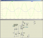
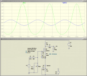
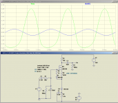
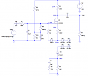
LTSpice seems to agree with my reasoning in my last post. See attached screenshots. (Note these are just LTSpice simulations right now - not built and tested and verified to work.)It would be interesting to see if they translate to low voltage in a convincing manner.
I've changed the positive supply rail to only 30V. The drain resistor has been changed so the drain sits at about 15V DC quiescent. I used a 5V negative supply because 5V USB chargers are everywhere now and will work perfectly to provide the -5V supply rail.
Id is a bit under 1 mA.
KMG's stuff at the FET source has been slightly simplified - no Schottky diodes, just 1N4148s.
Small-signal gain is only about 3.5 times (11 dB). As predicted earlier, this will be the major compromise with drastically lowered supply voltage. But the low gain is necessary to maintain headroom at the lower B+, anyway.
The output waveform is shown for three input levels: 10 mV peak, 350 mV peak, 700 mV peak. It seems to look about right, but I don't know how it will sound until I listen to it.
The circuit will accept 1.5 V peak input without clipping (3 volts peak-to-peak.)
In the simulation, hard (and probably unpleasant-sounding) clipping occurs at 4V peak to peak input.
This seems plenty to cope with maximum guitar output under realistic conditions. (I'm still shocked at Michael Koster's 10V peaks, but I think most of us won't get past ten percent of that.)
There should probably be a clean gain stage ahead of the circuit shown here for use with an actual guitar. The circuit works as shown when fed from a low-impedance signal source, so a buffer will be required with an actual guitar, and I suspect some gain would be a good idea, too, if useful distortion is wanted without having to whale on the guitar strings with a sledge-hammer.
I should probably mention that clean transparent gain and buffering is trivially simple with today's solid-state components. We can probably get what we want out of a single JFET stage ahead of the KMG stage shown in this post (tweaking the 68k in the attached schematics to allow for the output resistance of the JFET.)
In fact, transparent-clean gain stages can be sprinkled through as necessary. KMG-stages to generate "tubeyness", clean solid-state stages to bring up the gain if necessary, without changing the sound otherwise.
-Gnobuddy
Attachments
We are discussing the use of fets and other parts to build a circuit that emulates a tube......why not just use a tube, or a tube and a fet?
There are subminiature tubes that were made for everything from hearing aids to missile guidance systems. I have been tinkering with some of them for two specific purposes, A preamp that can fit inside a guitar and run for hours from a small battery, and for modules in a Eurorack synthesizer. Both have space and power requirements in line with sand state design, but there are some tubes that should be useful, all are priced around $1 to $2:
The 6418 consumes little power. The DH filament draws 10 mA from 1.25 volts. Plate voltage? 30 volts MAXIMUM, 15 to 22.5 recommended. Power output, 2 or 3 milliwatts. The issue, microphonics. Not such a big deal if mounted inside the guitar. It adds some "air" to the sound. Not for use in a combo amp!
The 6088 consumes a bit more power, and is far less microphonic since it has a thicker filament. It needs 20 mA at 1.25V. Max plate voltage, 67.5 although I have tested it to 125 volts without issue. Recommended B+ voltage, 45 volts, but it works good on 25 volts and still amplifies on 9 volts. Power output, a big 10 milliwatts!
The 5678 is the big boy here. Its filament needs 50 mA, and it's plate is rated for 90 volts, but I still didn't go beyond 125 V. It was made for RF use, hence no power output spec.
I'm looking at these for audio amplifier use, and all 3 make good triodes. The triode curves are in the data sheets.
You can operate them as a pentode with a mosfet load / buffer like I did in my HBAC Amp 1.5. The gain can be turned way up for some super saturated sounds, but microphonics become an issue with any tube when the stage gain gets into the hundreds.
There are all flea powered directly heated tubes. There are also a whole bunch of indirectly heated tubes that have 6.3 volt heaters, but they are beyond my power budget (I need a tube per string for piezo saddles), and probably that of a battery powered pedal.
I have one Takamine acoustic guitar that came with the manufacturer's "Cool Tube" piezo preamp. It uses a 12AU7, runs off four AA cells, and a fresh set of cells lasts for an incredibly long time. I bought the guitar in 2014, and didn't replace the original Japanese-made AA cells until the end of 2017 (though admittedly, this guitar didn't get a lot of plugged-in playing time for much of that period.)...A preamp that can fit inside a guitar and run for hours from a small battery
I don't have a schematic for the Cool Tube preamp, so I don't know what Takamine actually designed the tube to do. The "cool tube" name is supposedly to reassure you that there isn't a hot vacuum tube baking the moisture out of your precious guitar's wooden body. The insanely long battery life suggests there isn't a whole lot of power going to the heater. And I don't know if there is any internal boost converter, or the 12AU7 only has 6V on its anode.
What I do know is that this particular guitar has less of that harsh piezo sound (some call it "piezo quack") than most piezo-equipped guitars I've heard. Whether the 12AU7 is actually responsible for that or not, I don't know.
-Gnobuddy
I bought a few of those back around 2010 or so, when I had just made the earthshaking discovery that the awful electric guitar tone I'd had for 25 years, had been cured 30 seconds after plugging into my first valve guitar amp.There are also a whole bunch of indirectly heated tubes that have 6.3 volt heaters
I put them away not long after I bought them, once I realized I really didn't have a clue how a valve guitar amp worked its magic (I knew something about solid-state Hi-Fi audio electronics, sure, but those sounded awful for guitar...)
It's been a while since I looked at those little subminiature tubes, but I think I have a couple of triodes, a small-signal pentode, and a couple of 5902 4-watt power "pentodes" (which are probably actually beam tetrodes.)
Do we know if the guts of any of the indirectly heated subminis came from pre-existing larger valves? It would be funny if it turned out a 5902 is just a repackaged 6AS5 or something similar (with tweaks to make it resist high G forces and what not).
-Gnobuddy
Balanced line out - tips?
The guitar amp I've built for my friend is, like all engineering designs, a set of compromises. In order to keep it light (for my friend) and affordable (for me), I used boom-box speakers, which will limit the maximum SPL available.
I think it'll be loud enough for my friend 99% of the time, but for that last 1%, I'm thinking of adding a balanced XLR output. If he ever wants more loudness than the amp can provide on its own, he can use that to plug into the P.A.
Since the de-nastifying filter already has appropriate EQ / speaker emulation in it, this should be a pretty simple matter, i.e. I just need to tap off the signal at the output of the de-nastifying filter, and send that to the XLR jack.
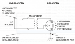
However, this is one of those things I've never actually designed or built before. I want to avoid ground-loop issues, and make sure the signal level is in the right ballpark to plug into a microphone input of a mixer.
Anyone have any tips on how to do it? Should I use a signal transformer? If so, what kind? What sort of circuitry does it take to drive said signal transformer (i.e. expected primary impedance and signal level?)
I'm attaching a screenshot taken from a Rane document on "sound system interconnection" ( Sound System Interconnection ). Does this look like the way to go?
Thanks in advance,
-Gnobuddy
The guitar amp I've built for my friend is, like all engineering designs, a set of compromises. In order to keep it light (for my friend) and affordable (for me), I used boom-box speakers, which will limit the maximum SPL available.
I think it'll be loud enough for my friend 99% of the time, but for that last 1%, I'm thinking of adding a balanced XLR output. If he ever wants more loudness than the amp can provide on its own, he can use that to plug into the P.A.
Since the de-nastifying filter already has appropriate EQ / speaker emulation in it, this should be a pretty simple matter, i.e. I just need to tap off the signal at the output of the de-nastifying filter, and send that to the XLR jack.
However, this is one of those things I've never actually designed or built before. I want to avoid ground-loop issues, and make sure the signal level is in the right ballpark to plug into a microphone input of a mixer.
Anyone have any tips on how to do it? Should I use a signal transformer? If so, what kind? What sort of circuitry does it take to drive said signal transformer (i.e. expected primary impedance and signal level?)
I'm attaching a screenshot taken from a Rane document on "sound system interconnection" ( Sound System Interconnection ). Does this look like the way to go?
Thanks in advance,
-Gnobuddy
Attachments
I've made an initial prototype of KMG LND150 gain stage, with fixed bias and Leo Fender cathode resistor (1k5). Actual components, not simulation.
For reference:
http://milas.spb.ru/~kmg/files/projects/jcm800mv/fet/lnd150/jcm800mvfSch.pdf
and see attached schematic for my changes.
Power Supply: I discovered an extra 1:1 isolation transformer in one of my parts boxes, so I made a half-wave voltage doubler. For now, I use a variac so I can adjust the output to 300VDC under load
Parts substitutions: For the parallel BAV70 pair, I use a single 1N914, for the BAT54S schottkys I use through hole BAT85S, For the ES1J high voltage fast recovery diode, I use UF4007.
Fixed Bias: Instead of referencing the LND150 gate to ground, it goes to a 270k/2k7 voltage divider. The LND150 source circuit is referenced to ground instead of a negative supply. This setup requires capacitor coupling the input signal, so I use 22n.
DC operating point:
I fed a 400hz sine wave at various voltage levels, and monitored output with a scope. I measured gain with a 100mV peak-to-peak input signal, so there would be no clipping.
Note: my scope doesn't have fancy digital readouts, so gain measurements are by eyeball, so consider them "ballpark" figures. I do all AC measurements by peak-to-peak values on my scope, it's easier that way.
So here, LTspice is a little optimistic with gain, versus a real circuit.
LTspice said a 910R bypass resistor for a gain of 60. Reality said a 470R resistor for a gain of 58.
So this resistor is "adjust on test".
Next, I gradually increased the input signal to overdrive the gain stage. From what I could tell, with my less than stellar scope, here's what happens:
For giggles, I put a 220R in place of the 180R hanging off the Source. It changed the DC voltages slightly, but didn't seem to make a difference in the AC characteristics. Again, my scope is not the most accurate thing in this world.
I'm sure the "grid current" threshold does change slightly, but not radically.
I couldn't tell the difference. The output waveforms behaved the same as with the 180R.
KMG uses 180R, 200R and 270R in his preamp. I'd say 220R is ok too.
I have not yet applied an actual guitar signal to this and listened to it. I don't expect just one stage will have any "magic", it needs a complete preamp. Just this one stage used up most of my little breadboard, it's a fragile mess, so I need to build on perfboard next.
Overall, the experiment worked out, at least from a DC operating point and sine wave perspective. No smoke, no surprises. Pretty darn close to what a 12AX7 would do in similar circumstances.
The question remains whether the 270k/2k7 voltage divider can be used for multiple gain stages, or if it needs a separate divider for each gain stage. Probably needs a separate one for each. We are after all simulating "grid current" here and the current has to come from somewhere. So connecting multiple gain stages to a single divider might be a recipe for oscillation, or not? It could do something really cool or not make any difference?
For reference:
http://milas.spb.ru/~kmg/files/projects/jcm800mv/fet/lnd150/jcm800mvfSch.pdf
and see attached schematic for my changes.
Power Supply: I discovered an extra 1:1 isolation transformer in one of my parts boxes, so I made a half-wave voltage doubler. For now, I use a variac so I can adjust the output to 300VDC under load
Parts substitutions: For the parallel BAV70 pair, I use a single 1N914, for the BAT54S schottkys I use through hole BAT85S, For the ES1J high voltage fast recovery diode, I use UF4007.
Fixed Bias: Instead of referencing the LND150 gate to ground, it goes to a 270k/2k7 voltage divider. The LND150 source circuit is referenced to ground instead of a negative supply. This setup requires capacitor coupling the input signal, so I use 22n.
DC operating point:
- Drain: 196V This is close to a Leo Fender stage where the plate sits at roughly 2/3 of B+. So we're getting about 1mA current through the 100k Drain resistor.
- Gate: 2.71V
- Source: 3.38V
This gives a Vgs of -0.67V. This is reasonably close to what you would get drawing a load line with the LND150 "output characterists" curves. - Top of Source diode chain: 3.20v
- 1k5 resistor: 1.48v
So the diode chain drops 1.72v @ 1mA. This seems reasonable for 4 schottkys and one regular silicon diode.
I fed a 400hz sine wave at various voltage levels, and monitored output with a scope. I measured gain with a 100mV peak-to-peak input signal, so there would be no clipping.
- With the 1k5 source resistor unbypassed, the gain was about 32.
- Fully bypassed, the gain was about 80.
- Bypassed with a 470R resistor in series with the bypass cap, gain of 58.
Note: my scope doesn't have fancy digital readouts, so gain measurements are by eyeball, so consider them "ballpark" figures. I do all AC measurements by peak-to-peak values on my scope, it's easier that way.
So here, LTspice is a little optimistic with gain, versus a real circuit.
LTspice said a 910R bypass resistor for a gain of 60. Reality said a 470R resistor for a gain of 58.
So this resistor is "adjust on test".
Next, I gradually increased the input signal to overdrive the gain stage. From what I could tell, with my less than stellar scope, here's what happens:
- As the input signal increases from 100mV, the output looks like a sine wave and gets bigger, as expected.
- At around 1Vpp input, the bottom of the output waveform starts looking less sine wave like, a little "peakier". It's still rounded, and it will stay rounded even under massive overdrive. This appears to be the threshold of "grid current".
- Around this time, the top of the output waveform increases a little less than the bottom.
- At around 3Vpp input, the top of the waveform increases no further. It is technically clipping at this point, but the leading and trailing edges are still very rounded. Bottom of waveform still rounded, and now increases slower.
- At 4Vpp input, obvious clipping on the top, bottom is still rounded. The duty cycle is changing.
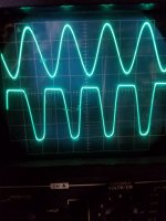
- At 6Vpp input, the duty cycle changes even more, the top clipping is more pronounced, but still with slighly rounded leading and trailing edges. See attached photo. Pardon the crappy photo, but you get the idea.
- At 12Vpp input, the trend continues, more (or less?) duty cycle, bottom still rounded.
For giggles, I put a 220R in place of the 180R hanging off the Source. It changed the DC voltages slightly, but didn't seem to make a difference in the AC characteristics. Again, my scope is not the most accurate thing in this world.
I'm sure the "grid current" threshold does change slightly, but not radically.
I couldn't tell the difference. The output waveforms behaved the same as with the 180R.
KMG uses 180R, 200R and 270R in his preamp. I'd say 220R is ok too.
I have not yet applied an actual guitar signal to this and listened to it. I don't expect just one stage will have any "magic", it needs a complete preamp. Just this one stage used up most of my little breadboard, it's a fragile mess, so I need to build on perfboard next.
Overall, the experiment worked out, at least from a DC operating point and sine wave perspective. No smoke, no surprises. Pretty darn close to what a 12AX7 would do in similar circumstances.
The question remains whether the 270k/2k7 voltage divider can be used for multiple gain stages, or if it needs a separate divider for each gain stage. Probably needs a separate one for each. We are after all simulating "grid current" here and the current has to come from somewhere. So connecting multiple gain stages to a single divider might be a recipe for oscillation, or not? It could do something really cool or not make any difference?
Attachments
I wonder if a single 1N914 could replace a pair of BAT85S?for the BAT54S schottkys I use through hole BAT85S
It seems wasteful to put four Schottky diodes in series if there is some other kind of diode that produces about the same voltage drop and dynamic resistance (they all seem to follow the same exponential curve at these low currents, so they really should have the same dynamic resistance if they have the same voltage drop at the same current.)
Maybe one LED, and one UF4007 in series for high-voltage protection?
Sounds good! You just reminded me that I totally forgot to buy any fast, high-voltage diodes when I bought Schottky diodes to try KMG's ideas out. Drat!For the ES1J high voltage fast recovery diode, I use UF4007.
I found the LTSpice model for the MPF102 JFET to be way off from reality. It seems you're finding the same thing for the LND150 model.So here, LTspice is a little optimistic with gain, versus a real circuit.
Supertex provides an LND150 model, but the one I posted in this thread was tweaked by someone who found the factory model was a very poor fit to the published LND150 datasheet curves. But it seems it doesn't match your actual LND150 devices very well, either.
I wish I knew how to tweak LTSpice models to better match reality. It can't be that hard, but I haven't stumbled across any documentation on how those diode and FET models are created. Staring at the text inside existing LTSpice models hasn't been enough for me to figure out how they work.
Now that's a little annoying! There are a lot of components per stage, aren't there?Just this one stage used up most of my little breadboard
And once again I'm wondering if four Schottky in series can't be replaced by some smaller number of components.
My guess is that you can run at least a few stages off the same divider, especially if you increase the 100nF filter cap to maybe 10 uF or 100 uF instead. (Make it big enough, and you can simulate the heater warm-up time and slow turn-on of real valves!)The question remains whether the 270k/2k7 voltage divider can be used for multiple gain stages, or if it needs a separate divider for each gain stage.
I wonder if replacing the 2.7k with an appropriate LED might also be worth a try? The lower dynamic resistance of an LED (compared to a 2.7k resistor) might help with running more stages off the same voltage node.
True, but you have a 1 meg resistor between the FET gate and the 3V DC node, so you can't draw more than a few microamps of current from your 3V DC source.We are after all simulating "grid current" here and the current has to come from somewhere.
That's why I suspect you can feed a number of stages from that same point, as long as the dynamic impedance to ground is low enough not to create any unwanted feedback.
A 100nF cap has a rather large 20 kilo-ohm reactance at 80 Hz (guitar low E), so it really isn't helping filter that node much - the 2.7k resistor is a lower impedance than the capacitor over most of the guitar frequency range.
But a 100uF cap will get that reactance down to 20 ohms, which I think should be negligible in that circuit.
Thanks for sharing your results so far! I look forward to reading about your future developments - it will be interesting to see if KMGs ideas work to create good Fender Blackface clean tones.
I think the clean tones I liked from KMGs FET Bogner Ecstasy were actually from his 2SK216 MOSFET amp, rather than his later LND150 one. The circuit was a bit different too ( http://milas.spb.ru/~kmg/files/projects/xtcfet/XtcFet.pdf ), with one source diode and apparently no grid-current emulation.
So I'm very curious if his later LND150 circuitry provides equally good (or better) clean tones.
-Gnobuddy
Member
Joined 2009
Paid Member
So I'm very curious if his later LND150 circuitry provides equally good (or better) clean tones.
-Gnobuddy
If you are looking for low distortion for 'clean' then with most FETs (all ?) the linearity will improve with standing current. If you can keep the little thing cool then increasing current will buy more linearity. You can also fine-tune the source degeneration resistor for linearity (load line). But for a guitar amp, I really doubt it's going to be audible once you have the device operating at a reasonable current level to start with.
The trouble is that the FET circuits I've tried have all been too linear, so they sound too clean (tending towards lifeless and sterile, like so many solid-state guitar amps.)If you are looking for low distortion for 'clean' then with most FETs (all ?) the linearity will improve with standing current.
It seems we have to do something to make them less linear, in a good way, if we want to come close to what valves do naturally.
I estimated 35% second harmonic distortion for the good-sounding "clean tones" from my DIY valve preamp with a 6AG5 final preamp stage ('scope screen capture was posted earlier.) I have been having trouble squeezing anywhere near 35% out of a JFET.
I found some posts by KMG in another forum, and he provided a link to the following clip, with the statement that it came from his MOSFET version of the Bogner Ecstacy: http://milas.spb.ru/~kmg/files/projects/xtcfet/pedal/samples/denn/kmg_xtc_mix.mp3
Those sound like pretty decent guitar clean tones to me. I think the circuit that created those "clean tones" (which are not clean at all in Hi-Fi terms, but incorporate enough distortion to sound good for guitar) is this one, using 2SK216 MOSFETs and an earlier evolution of his triode-emulation circuit: http://milas.spb.ru/~kmg/files/projects/xtcfet/XtcFet.pdf
I don't fully understand this earlier form of MOSFET triode emulation either, but I think the diodes connected to the source of each MOSFET are there to lower transconductance and add nonlinearity, to roughly match what half a 12AX7 does.
-Gnobuddy
I tried that. Replaced 4 schottkys with 2 1N914.I wonder if a single 1N914 could replace a pair of BAT85S?
When overdriven, the leading and trailing edges on the top of the waveform are sharper, still not completely squared off, but not as soft as with the schottkys.
However for moderate signal levels, say 100mVPP to 1VPP, it's hard to tell the difference. The schottkys (all 4 of them) seem to be critical for simulating the 12AX7 characteristic curves that get closer together near cutoff.
This isn't the first time I have found spice models to be offI found the LTSpice model for the MPF102 JFET to be way off from reality. It seems you're finding the same thing for the LND150 model.
Well I didn't have any LED's that would work out for the required voltage. I have some red ones at 1.6v and some green at 1.8v.My guess is that you can run at least a few stages off the same divider...
I wonder if replacing the 2.7k with an appropriate LED might also be worth a try? The lower dynamic resistance of an LED (compared to a 2.7k resistor) might help with running more stages off the same voltage node.
What does work is 4 x 1N914, gives around 2.8 volts, which remains fairly constant with fluctuations in B+ (I turn the variac up and down).
For my version of the circuit (different diodes than KMG and fixed bias), it looks like the sweet spot for the bias supply is around 2.75 volts give or take a tenth.
There are through hole 2.7v zeners, but I don't have any, but I do have a bag of 1N914 so will probably go with those for now.
You and me both. I've still got a lot of work to do with this, but the important first steps have been taken.I think the clean tones I liked from KMGs FET Bogner Ecstasy were actually from his 2SK216 MOSFET amp, rather than his later LND150 one. The circuit was a bit different too ( http://milas.spb.ru/~kmg/files/projects/xtcfet/XtcFet.pdf ), with one source diode and apparently no grid-current emulation.
So I'm very curious if his later LND150 circuitry provides equally good (or better) clean tones.
Ah. Thanks for trying the experiment, and telling us how it turned out. Okay, four Schottky's it is!The schottkys (all 4 of them) seem to be critical for simulating the 12AX7 characteristic curves that get closer together near cutoff.
-Gnobuddy
It just occurred to me that an LND150 with a 100k anode resistor will probably have an output impedance of essentially 100 kilo ohms. But half a 12AX7 with a 100k anode resistor will have an output impedance of around 40 kilo ohms, two and a half times lower.
This is because the (internal) anode resistance of the triode is somewhere in the ballpark of 70 kilo ohms, much lower than the internal drain resistance of a modern MOSFET.
In other words, we can expect considerably more severe loading effects on one of KMG's triode-emulation stages, compared to the real thing.
-Gnobuddy
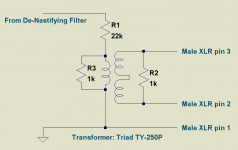
I added a line-out jack (actually a mic-level XLR male connector) to the amp, so my friend can plug it into the P.A. if he ever wants more volume than the pair of 6 1/2" speakers can put out.
This was pretty easy to do because the de-nastifying filter already removes all the nasty-sounding frequencies before they go to the internal class-D power amp module. So all I had to do was tap off the signal from the de-nastifying filter, pad it down to the right level, and add transformer isolation to prevent ground loop problems when plugging into the P.A.
It turns out Triad makes an isolation transformer with a full 20 Hz - 20 kHz bandwidth, and it works at impedance levels that are comfortable for both the de-nastifying filter and a typical microphone input on a mixer. It's affordable too, not like the platinum-and-diamonds Jensen mic transformers. (TY-250P Triad Magnetics | Mouser Canada )
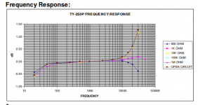
As you can see in the schematic, I wired a 1k resistor across the transformer primary, and another across the secondary. A glance at the attached transformer frequency response plot will make it obvious why I added the 1k resistors!
We tested the line-out at last night's jam, and it works very well. My wife commented that she had never heard our friend's playing as clearly as she did last night.
I think the amp is pretty much done now, and none too soon. I'm burned out from having spent all my spare time on this project for some months now.
I will get some photos of the completed amp next week, just to wrap up the story here.
-Gnobuddy
This was pretty easy to do because the de-nastifying filter already removes all the nasty-sounding frequencies before they go to the internal class-D power amp module. So all I had to do was tap off the signal from the de-nastifying filter, pad it down to the right level, and add transformer isolation to prevent ground loop problems when plugging into the P.A.
It turns out Triad makes an isolation transformer with a full 20 Hz - 20 kHz bandwidth, and it works at impedance levels that are comfortable for both the de-nastifying filter and a typical microphone input on a mixer. It's affordable too, not like the platinum-and-diamonds Jensen mic transformers. (TY-250P Triad Magnetics | Mouser Canada )
As you can see in the schematic, I wired a 1k resistor across the transformer primary, and another across the secondary. A glance at the attached transformer frequency response plot will make it obvious why I added the 1k resistors!
We tested the line-out at last night's jam, and it works very well. My wife commented that she had never heard our friend's playing as clearly as she did last night.
I think the amp is pretty much done now, and none too soon. I'm burned out from having spent all my spare time on this project for some months now.
I will get some photos of the completed amp next week, just to wrap up the story here.
-Gnobuddy
Attachments
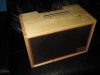
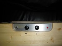
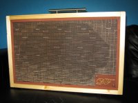
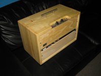
Here are some pictures to wrap up the project (building a guitar amp for a senior-citizen friend, on a tight budget.)
The logo plate (complete with the raised letters, which are my friend's initials) was 3D-printed out of white PLA (Polylactic Acid, a biodegradable thermoplastic.)
Then I spray-canned the logo plate a shade of brown that was chosen to go well with the grille-cloth, and used an oil-based gold paint marker to colour the raised letters.
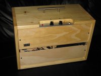
The male XLR connector on the back of the enclosure is the mic-level output, which can go straight into a mixer or P.A. system.
I've tested this, and it works well, sounds good, and is hum-free. I really like the way this feature turned out, and I think I might want to include it on my own guitar amp builds in future.
The gap between the two rear panels allows one to stuff the power cord neatly away for storage and transportation of the amp.
I might do some fine-tuning of voicing or gain in the future, based on any feedback I get from the mysterious owner (DF). But I consider the project done at this point.
That doesn't mean this thread is done, however. There were many interesting things brought up earlier in this thread that I wanted to try out, but did not have the time for. Now that DF's amp is done and out of my hands, I plan to investigate some of those things.
-Gnobuddy
The logo plate (complete with the raised letters, which are my friend's initials) was 3D-printed out of white PLA (Polylactic Acid, a biodegradable thermoplastic.)
Then I spray-canned the logo plate a shade of brown that was chosen to go well with the grille-cloth, and used an oil-based gold paint marker to colour the raised letters.
The male XLR connector on the back of the enclosure is the mic-level output, which can go straight into a mixer or P.A. system.
I've tested this, and it works well, sounds good, and is hum-free. I really like the way this feature turned out, and I think I might want to include it on my own guitar amp builds in future.
The gap between the two rear panels allows one to stuff the power cord neatly away for storage and transportation of the amp.
I might do some fine-tuning of voicing or gain in the future, based on any feedback I get from the mysterious owner (DF). But I consider the project done at this point.
That doesn't mean this thread is done, however. There were many interesting things brought up earlier in this thread that I wanted to try out, but did not have the time for. Now that DF's amp is done and out of my hands, I plan to investigate some of those things.
-Gnobuddy
Attachments
- Status
- This old topic is closed. If you want to reopen this topic, contact a moderator using the "Report Post" button.
- Home
- Live Sound
- Instruments and Amps
- Tube Emulation & EQ