I like that idea.This is the route I'd probably take:
1) 12V, 2A switching power supply:
2) 45V - 390V DC-DC boost converter for the high voltage:
3) 3.3V, 5W switching power supply for the -3.3V rail:
If things work out, I will likely go with switching supplies and a suitable enclosure.
The Hammond iron is way too big and heavy for the finished product.
Right now I just want to get a power supply going for prototyping purposes and I already have the needed components on hand.
Ok that's what I'll do, use a voltage doubler on the 6.3v filament winding.I like voltage doublers, they are a great solution for relatively lightly loaded supply rails.
Nice detective work! I think you've nailed it.However, the eyelet board of 5F6 and 5F6A is identical.
The tail resistor was a convenient place to attach the NFB, having rejected the idea of going to the bottom of the tone stack.
It is a very minor change to the layout, almost unnoticeable unless you're really looking for it.
So that would support Merlin Blencowe's theory.
")
Again, I think you've nailed it. I think Blencowe actually mentioned some of these issues in his book (tone controls in the feedback network, added grid stoppers, presumably in an attempt to combat instability.)But now, one wonders what was wrong with the 5F6?
Was it oscillating?
<snip>
5F6: 1k5 grid stoppers, 5F6A: no grid stoppers
<snip>
...Also possible weird interactions based on tone control settings. This may have caused oscillations.
Some things are awkward to calculate, and quick to do on the test-bench. Other things are the opposite. To me, it makes sense to use whatever method works best.So I just play with the feedback resistor until I get about 10db NFB, and call it a day.
I once worked on a motional-feedback woofer project, with the feedback voltage coming from a piezo disc mounted to the speaker voice coil. I really had no idea how much signal to expect from the piezo, or how to calculate it, if that was even possible.
So I did the same thing as you, first an open-loop frequency response sweep, then carefully dial in negative feedback until the gain drops by the appropriate amount.
I think you just put your finger on a key point: people who read schematics won't like the weird Fender feedback. But people who read physical layouts (and usually aren't comfortable with schematics) won't care.I will say that when you wire it "correctly" and stare at your schematic, it's a lot easier for your brain to figure out what is going on.
I was pretty surprised some years ago when I found out that a large proportion of the DIY guitar amp building community don't actually read schematics, and work directly from layouts instead. Same thing for DIY stomp-boxes.
-Gnobuddy
That's a great observation.I think you just put your finger on a key point: people who read schematics won't like the weird Fender feedback. But people who read physical layouts (and usually aren't comfortable with schematics) won't care.
And it may have something to do with the 5F6.
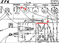
I took an additional look at the changes in NFB between 5F6 and 5F6A, but from the layout point of view, rather than the schematic.
Here is the 5F6 layout with the 5F6A mods in red:
When you look at it on the layout, it kind of looks like you are doing the "right" thing, as in "we need to put the NFB to the unused input of the LPT"
It is entirely possible Leo was indeed intending to do it the "right" way.
To "complete" the mod, he needed to lift the 10k tail resistor and run it to ground, but there was no extra eyelet to do so.
There was no "visual cue" that anything further needed to be done.
It's easy to overlook the 10k tail resistor in this situation.
I can totally see how that could happen. You are focused on getting the NFB to the right place, the tail resistor is not of immediate concern.
You mod a little, test a little, mod, test, and stop when it works.
Heck, I've done stuff like that a bunch of times, although my errors usually end in a puff of smoke rather than the most iconic guitar amp of all time.
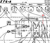
Here is the 5F6A circuit with the "completed" mod shown in red.
This is the "correct" way to do NFB to a LTP
The 5F6A method worked good, looked good on the eyelet board and Leo may have thought it was the "right" thing, because it kind of looked like the right thing, at least on the eyelet board.
The new schematic was drafted after the mod was performed, and Leo may have said
"Is that what we came up with? Well that's odd, but it fixed the problem. I'm done fooling around with phase splitters, this is what we are using from now on."
Attachments
And I think it is entirely possible you've solved the mystery. Sure your last name isn't Poirot?When you look at it on the layout, it kind of looks like you are doing the "right" thing, as in "we need to put the NFB to the unused input of the LPT"
It is entirely possible Leo was indeed intending to do it the "right" way.
Sorry for my recent absence from the thread. I had one of those little periods when the universe throws a few curve-balls at you to see how many you can dodge before she finally gets you in the solar-plexus with one.
So I (a) got sick again (nasty 'flu season this year) and have had no energy at all after work, and (b) put my back out so I'm hobbling around like a ninety-year-old.
Not satisfied with that, the universe then got me with one more little joke at my expense. My home computer borked itself after the last automatic security update (Xubuntu Linux).
The hardware is okay, it's just a software problem. I'm temporarily running it off a Linux live-USB (flash drive), but have deliberately disconnected the internal SSD (to make sure I don't accidentally trample on it while running the live USB). So for the moment, no access to my data.
Really it's nothing too serious, my data is still on the SSD, and I have reasonably recent data back ups as well. I just have to find a little time to deal with the mess properly, re-install Linux, and make sure I don't lose any of my data in the process.
And while mjd_tech was solving the mystery of Leonidas' bizarre feedback scheme, all I've done with my amp project is manage to drill a few holes in the aluminium control panel, and order the missing 500k linear pot for the tone control.
Hopefully there will be more progress this weekend!
-Gnobuddy
...Leo was using extremely crude +/- 20% resistors...
Well, no. You must not have spent much time inside vintage Fenders.
True, but all the schematic values are from the E6 range.Well, no. You must not have spent much time inside vintage Fenders.
More to the point, if he was using 10% resistors, that still allows up to 20% imbalance in a differential pair from resistor tolerance alone, plus maybe another 10% - 20% from triode mismatch...
-Gnobuddy
I finally got my PC back to normal yesterday. New SSD, lots of fighting with a stupid BIOS that insisted on booting from the wrong device no matter how I set the boot order, eventual success booting with a Linux live-USB and copying data files manually from the old borked install onto the new SSD.
For my first few tries the copy command would run along for a while, then fall over its feet . Investigation revealed one folder contained lots of file names with commas, caret (^) symbols, and even exclamation marks in them. Those characters tend to really confuse Linux, because they have special meanings to the BASH shell.
That one folder originally came from a friend, who, of course, works on Windows.
After much futzing, first with a Linux filename-cleaning utility called "detox", then some final manual cleanup, I finally got the data copying to work properly.
So now I have my data back. I hope. Fingers crossed that all the data copying went smoothly.
I made a little progress on the amp late last night. I clear-coated the small aluminum control panel in less than ideal conditions (cold and rainy). The class-D power amp module is mounted in the electronics cavity on the back of the amp. A quick 11 PM low-volume test with the guitar straight into the class D module revealed no obvious problems.
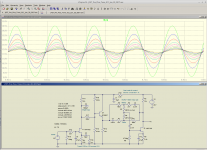
The de-nastifying filter is ready to go, but the JFET input is still in breadboard form. The tone control isn't built or tested yet, only simulated in LTSpice. So I'll work on some of that today.
I'll attach a schematic of what I'm planning. Remember, all FET source resistors shown on the schematic are wrong - these are the values LTSpice wants to bias up properly, but the actual FETs I have want something very different.
Oh yeah, the weird DC coupled bias network around the BJT buffer for the tone control is a combination signal attenuator and biasing network. It's DC coupled to reduce space needed on the little protoboard. Attenuation has been set to produce around 5Vpp from the tone control output at full boost (either 80 Hz or 5 kHz), with 1.5V pp input from the guitar.
There is a similar not-quite-kosher DC coupling in the tone control. But resistor values are large, and unwanted leakage currents due to the DC coupling will be in the 1 uA range.
-Gnobuddy
For my first few tries the copy command would run along for a while, then fall over its feet . Investigation revealed one folder contained lots of file names with commas, caret (^) symbols, and even exclamation marks in them. Those characters tend to really confuse Linux, because they have special meanings to the BASH shell.
That one folder originally came from a friend, who, of course, works on Windows.
After much futzing, first with a Linux filename-cleaning utility called "detox", then some final manual cleanup, I finally got the data copying to work properly.
So now I have my data back. I hope. Fingers crossed that all the data copying went smoothly.
I made a little progress on the amp late last night. I clear-coated the small aluminum control panel in less than ideal conditions (cold and rainy). The class-D power amp module is mounted in the electronics cavity on the back of the amp. A quick 11 PM low-volume test with the guitar straight into the class D module revealed no obvious problems.
The de-nastifying filter is ready to go, but the JFET input is still in breadboard form. The tone control isn't built or tested yet, only simulated in LTSpice. So I'll work on some of that today.
I'll attach a schematic of what I'm planning. Remember, all FET source resistors shown on the schematic are wrong - these are the values LTSpice wants to bias up properly, but the actual FETs I have want something very different.
Oh yeah, the weird DC coupled bias network around the BJT buffer for the tone control is a combination signal attenuator and biasing network. It's DC coupled to reduce space needed on the little protoboard. Attenuation has been set to produce around 5Vpp from the tone control output at full boost (either 80 Hz or 5 kHz), with 1.5V pp input from the guitar.
There is a similar not-quite-kosher DC coupling in the tone control. But resistor values are large, and unwanted leakage currents due to the DC coupling will be in the 1 uA range.
-Gnobuddy
Attachments
I started with that idea, but that would allow the tone control circuit to be clipped if the (guitar) input was driven hard.Why don't you connect the base directly to drain, omitting 3 resistors?
In an active tone control, clipping is not good: open loop gain falls to zero during clipping, so negative feedback disappears, so the entire tone-control characteristic disappears. You get nasty clipping, and no tone control, at the same time!
The tone control itself has a maximum gain of about 12 dB, so the only way I can be sure it won't ever clip, is to make sure that there is some 12 dB of signal attenuation between the input JFET and the tone control. That way, the input JFET can be in full clipping, acting as a limiter, and the active tone control still won't clip.
The weird 3-resistor network is a way to keep the DC voltage on the BJT at essentially half B+, simultaneously create some signal attenuation, and not use a coupling capacitor. Thevenin impedance of the 3-resistor network at the BJT base is a lot less than 330k, I think closer to 100 kilo ohms.
I will do some tinkering on the breadboard to see if the 330k can be reduced without the tone control getting clipped in practical use.
Incidentally, so far, noise hasn't been an issue with this amp. Probably because it cannot be turned up to 110 dB SPL like most guitar amps can! With boombox speakers and maybe 35 W RMS total power, it doesn't get loud enough for hiss to be audible.
-Gnobuddy
There should be better ways to reduce input gain if required.
For instance raising source impedance of input JFET.
I see no point in attenuating drain voltage of JFET input stage.
If your Emitter-follower clips, the preceeding JFET will clip as well, or am I missing something?
For instance raising source impedance of input JFET.
I see no point in attenuating drain voltage of JFET input stage.
If your Emitter-follower clips, the preceeding JFET will clip as well, or am I missing something?
..all the schematic values are from the E6 range.
More to the point, if he was using 10% resistors...
Look at the layouts in mjd_tech's #263.
82K is E12.
Key resistors are noted 5%.
Anyway the typical result of a 20% deviation of resistor on a tube (any simple active device) is 10% difference of gain and overload. Only very high NFB amps' NFB resistors directly set gain.
The 5% for the 100K/82K plate pair seems silly to me. However Fender mostly heard these builds fitted with tubes fresh from RCA/GE in their best years (and later, run for their now-best customer) so a random-grab from a case of 10,000 6L6 really would usually give a pair matched well enough to just-tell the long-tail's residual unbalance.
Leo is no tone-god. The 5F6a reeks of mistake after mistake; he got lucky. Most guitar amps have worse mistakes: the Traynor BassMate overloads teh 2nd stage too easy, nobody can grok the fancy EQ on the high-end Ampegs. The Bassman speaker system truly sucked in its intended market. As you note, Leo's guitars were pedestrian and the iconic axes are by others. But his products and marketing were clearly better than anybody except Marshall.
True, but all the schematic values are from the E6 range.
Fender specified 5% resistors for the 82k and 100k plate resistors in the 5F6 long tail pair.
91k would have been a better choice than 82k, but in 1959, 5% resistors in the E12 series were probably too expensive for Leo's tastes.
Fender did use 91k in some of the more recent (post-CBS) amps.
For what it's worth, I've tried both the 82k and 91k in the same amp and didn't notice a big difference, if any.
The ratio of Rd/Rs sets DC operating point, so I can't raise Rs without raising Rd to match.There should be better ways to reduce input gain if required.
For instance raising source impedance of input JFET.
The actual values that worked on my breadboard are 10k for Rs, 47k for Rd. The LTSpice model for the MPF102 doesn't match my actual MPF102 well, so I had to use a different value in LTSpice.
Small-signal gain of that input stage is around 4 (maybe a little higher). I settled on George's guitar 'scope capture earlier in this thread, showing about 1.5 volts peak-to-peak, as an expected maximum input level. With a gain of x4 and B+ of around 20 - 22 volts, the input stage should handle that without trouble.
I may be able to raise the input stage gain a little more, but the circuit as shown was tested and it worked to reduce the harshness from the guitar.
(Exactly why this worked to reduce harshness, is still a little bit of an unsolved mystery. I don't know exactly why. Predicted steady-state THD is quite low, so my guess is that it has more to do with compressing the big initial transient voltage at the start of each guitar note. But that's only a guess; the other possibility is that I have simply allowed my mind to trick me into hearing what I wanted to hear. Of course, I don't believe that yet. But I haven't conducted a double-blind listening test, either!
)I don't think you're missing anything, but the input stage can clip without causing any obvious problems, other than the usual guitar overdrive / distortion (which is desirable, if anything).I see no point in attenuating drain voltage of JFET input stage.
If your Emitter-follower clips, the preceeding JFET will clip as well, or am I missing something?
But if the active tone-control stage clips, the frequency-dependent negative feedback goes away during clipping, which means the frequency response of the stage is no longer set by the feedback network. So you not only get clipping, but along with it, wild and unwanted changes in EQ. The tone control stops working as a tone control, in other words.
I suppose it's possible that this might (by chance) sound good, but my first thought is to make sure the active tone control never clips.
Coming to guitar amps from a Hi-Fi background, throwing away gain between stages with resistive attenuators, which is quite common in higher-gain guitar amps (not Leo's old classics), seemed completely mad to me at first sight.
Eventually I understood this is all in the pursuit of deliberate non-linearity and distortion, something that simply doesn't apply in (sane) Hi-Fi engineering.
If you drive one gain stage hard enough to generate the nonlinearities that are desirable for guitar, then you usually have too much output signal to drive the next stage. So you deliberately throw away gain with resistive attenuation in between gain stages, then add another gain stage to create more of the (desirable) distortion.
Gain, loss, gain, loss. It seems mad, but actually makes sense in context!
Thermal noise is an other head-scratcher when switching from Hi-Fi to guitar amps. Inside many of my guitars, there is a 500k volume pot. Set to half-resistance (250k between each end and the wiper), Thevenin source impedance would be one-quarter of that, i.e. 125k, if the pickups had zero impedance of their own. Since the pickup itself has several kilo ohms of DC resistance, the resistive part of the guitar source impedance can actually go higher than 125k.
Thinking in Hi-Fi terms, that should create a horrifying amount of completely unnecessary thermal noise. But in practice, with my guitar amps, I can't hear any increase in hiss with the guitar volume pot set near mid-point.
I can only conclude that the thermal noise elsewhere in these amps (input triode, etc) is bigger, and swamps out the thermal noise from the guitar volume pot itself.
To be clear, I certainly don't know the "best" way to make a JFET preamp for electric guitar. I'm feeling my way forward here, one step at a time. There have been some clear and immediate successes (such as the "de-nastifying filter"). And some fumbling around mostly in the dark (still-untested tone control circuit.) And a few things in between, like the JFET input stage that seems to reduce audible harshness according to my ears, but my brain still doesn't know exactly why it works.
-Gnobuddy
If you want some kind of overdrive in the JFET, you may add the attenuator to match to the following EQ-stage.
But if you you want a max clean sound, you can reduce input gain by source impedance, i.e. raise the ac-coupled source resistor.
There is no impact on bias setting in doing so.
And concerning noise - it is true that input noise often is dominated by the following gain stages.
Which tells us they are far from optimum.
But who cares?
On some records of Jimi Hendrix the 60Hz hum captured by the single coils of his strat is obviously present.
I emphasize on a real low noise guitar with stacked humbuckers and an active vol-pot which yields a phantastic dynamic range - but that's me.
Last edited:
Arrgh! My apologies - that AC coupled resistor doesn't exist in the actual circuit, and I completely forgot to mention this earlier....you can reduce input gain by source impedance, i.e. raise the ac-coupled source resistor.
Let me explain. For my actual MPF102, on the breadboard, Rs is 10k. LTSpice wants 16k instead to achieve the same bias point.
So, in LTSpice, I AC-coupled a 27k resistor in parallel, effectively creating a 10k source resistance, so that predicted voltage gain would be a bit closer to reality.
Exactly!Which tells us they are far from optimum.
But who cares?
Heck, if we cared about optimum thermal noise, we certainly wouldn't be using an input device heated to nearly 1300 degrees Kelvin! That means about double the thermal noise voltage compared to a room-temperature device like a BJT or FET!
Most of my guitars have humbuckers for this reason - I don't like the sound of AC hum.On some records of Jimi Hendrix the 60Hz hum captured by the single coils of his strat is obviously present.
But I do miss the unique sound of a 'Strat, so I might have to break down and get one some day. Probably a Squier Deluxe, which in my experience have better quality and lower price than the Fender-labelled Mexican-made ones.
With a 'Strat, I usually end up with the pickup selector in one of the "humbucking" positions, combining outputs from two single-coil pickups.
I experimented with this sort of "Hi-Fi" approach to electric guitar when I started out, and I've heard it on some '80s recordings, often with solid-state amps.I emphasize on a real low noise guitar with stacked humbuckers and an active vol-pot which yields a phantastic dynamic range - but that's me.
But over the years, I've gradually come around to more or less the traditional approach with electric guitars. It seems to produce the sounds I enjoy most.
Case in point, the current amp project's "de-nastifying filter" peaks at 2 kHz and rolls off above that. That seems shockingly low compared to the 20 kHz minimum in Hi-Fi, but my ears say that this sounds about right with my electric guitars.
Published guitar speaker frequency responses usually seem to go an octave or so higher - but that is the on-axis response. I don't know anyone who listens to an electric guitar amp with their ears on-axis to the speaker - usually that sounds horribly harsh and bright. Often the guitarist has the amp pointing at his/her calves while setting the amps tone controls, rather than at his/her ears.
So what happens off-axis, and a more typical listening position? Maybe a roll-off at 2 kHz, like the one I found by trial and error for this amp?
-Gnobuddy
Right you are, and I made a mistake saying 91k is E12, it is E24.82K is E12.
Using a 12AX7 long tail pair to drive 5881 or 6L6 is silly too, if your goal is "distortion free amplification", as the marketing literature claimed.The 5% for the 100K/82K plate pair seems silly to me.
The 12AT7 is a better choice for this application.
And Fender did indeed go this route in the AB763 series.
So why didn't Fender go with 12AT7 from the start?
It is likely in 1959, Fender wanted to standardize on the 12AX7 and they were still using surplus 12AY7 from the earlier tweed era.
Fender probably did not want to bring another valve into the mix just yet. Thus the decision to use the 12AX7 splitter in 1959 and through the brownface era.
The 12AT7 makes its first appearance as the pre-amp in the 6G15 Reverb unit in 1961.
By this time, 12AY7 were off the Fender roster.
The 12AT7 becomes the standard phase splitter in the AA763 with 27k tail, quickly changed to AB763 with 22k tail.
See the "Leak TL/12 Plus" phase splitter, very similar.
Since Fender now had to stock 12AT7, they also chose that for the reverb driver in the AB763 reverb amps.
We often talk about the famous 5F6A Bassman, but similar is the 5F8A Twin. Almost identical circuit, with the Twin having 4 5881.
It's possible the R&D work was actually done on the Twin and backported to the Bassman, I believe the Twin was the "top of the line" model at that time.
Leo was using extremely crude +/- 20% resistors from the E6 series, meaning his LTP balance would vary wildly from one amp to the next, up to a worst-case 40% mismatch.
If Leo had wanted to use, the less common at the time, 10% or 5% resistors, wouldn't he have used used 100+91k instead of the 100k+82k load resistors, for better PI balance?Well, no. You must not have spent much time inside vintage Fenders.
This even if he had the most magical feedback scheme in the world. There is simply no way to ensure LTP balance when the triodes and resistors Leo used had these sorts of huge statistical parameter variations. There is also the fact that a perfectly balanced phase splitter would still inevitably be followed by imperfectly matched output valves, and an imperfectly symmetrical output transformer. The output of the amp would still contain lots of imbalance.
Yes, I think that's fairly obvious. However, you can compensate the imbalances with this clever little feedback loop from the OT back to the PI. Here's how it works. With a perfectly balanced LTP PI, any signal injected into the tail, will appear equally at both anodes. Followed by a perfectly balanced (mythical) power amp, the resulting signal would then cancel out in the OT.
But as we know, neither the PI nor the PA are perfectly balanced, so artifacts of the imbalance will appear at the final output. NFB from the OT back into the PI tail will then be effective to reduce those artifacts. That's at least what I think Leo was really up to.
As I'm not a Fender phanboy, none of this has ever worried me at all.There is a great deal of Fender lore that doesn't stand up to closer scrutiny. I mean no offense to anyone who's believed some of it, but if we are to make any progress in guitar amp design, we have to sort out the myths from the cold, hard, often unromantic, engineering reality.
Me too! A slightly unbalanced PI with imperfectly matched power tubes suits me just fine.Personally, I prefer the sound of a push-pull amp with at least 1 dB (approx 12%) imbalance, either in the phase splitter or output stage.
Unfortunately, it doesn't appear that Leo Fender was of the same opinion, as his amplifiers evolved with minimizing distortion. So maybe some time I'll try disconnecting the cathode feedback on a Fender amp, if I can find an owner who would let me!Now that I look at this further, he may have used the 82k instead of the 91k because he was using a tail resistor of 10k.If Leo had wanted to use, the less common at the time, 10% or 5% resistors, wouldn't he have used used 100+91k instead of the 100k+82k load resistors, for better PI balance?
The 12AX7 will be pretty well balanced in a LTP, provided the tail resistor is high enough.
See the Mullard 5-10:
Mullard 5-10. Ten Watt Amplifier
It is necessary in a cathode-coupled phase splitter for the anode load of the earthed section to be slightly higher than that of the first section if perfect balance is to be obtained. Thus R10 should ideally be slightly higher than R9, by a percentage which depends on the amplification factor of the valve. Because of the high amplification factor of the ECC83, nominally equal resistors, matched to within 5%, cannot give rise to more than 2% lack of balance.
Why a 10k tail?
Headroom. Leo was driving 6L6/5881. Mullard and Vox - EL84, an easy to drive valve.
I'm pretty sure Fender abandoned the 12AX7 cathodyne circuit prior to 5F6 because of headroom issues. Probably the cathodyne was not allowing full swing on the grids of the output tubes, so the amp wasn't delivering full power.
I could be totally wrong here, just offering some ideas.
Since the direction of imbalance is random, I would have thought there was a 50/50 chance that feedback to the PI tail would make the unbalance worse, rather than better......artifacts of the imbalance will appear at the final output. NFB from the OT back into the PI tail will then be effective to reduce those artifacts.
My gut instinct is that Merlin Blencowe, and mjd_tech, are both right: Leo, or his tech, changed the feedback scheme for stability reasons, and did what was easiest to do with the existing eyelet-boards.
Since I haven't actually tried writing down the loop equations for Leo's weird feedback and solving them manually, mebbe it's worth running a quick little LTSpice simulation to see what good, if any, occurs.
(Since same-name devices are all perfectly matched in LTSpice, my first thought is to just using two different N-channel JFETs instead of triodes to simulate imbalance in LTSpice.)
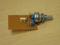
Meantime, I have finally made a little more progress on my project (see pic). The tiny proto-board holds the tone control pot, and the passive components needed for the active tilt tone control. That is a 13 mm (half-inch) Alpha pot, with a metal shaft, and good control feel.
The last bit of electronics will be to put together the input JFET stage, the BJT emitter-follower to buffer the tone control, and the JFET for the active tone control itself. That will go on another little board, possibly soldered direct to the 1/4" input jack.
Now that the tone control is almost done, I'm wondering, is there any kind of standard as to which way a tilt tone control should work? More bass at full clockwise, or more treble?
My first thought is more treble as you turn clockwise, which is usually the way the "tone" knob on a guitar is wired. That should cause less confusion for my senior-citizen friend when he finally starts using the amp...his guitar and his amp will have tone controls that turn the same way to produce the same effect.
Your thoughts?
-Gnobuddy
Attachments
- Status
- This old topic is closed. If you want to reopen this topic, contact a moderator using the "Report Post" button.
- Home
- Live Sound
- Instruments and Amps
- Tube Emulation & EQ