Exactly! I saw brass and stainless kick-plates at the Home Depot where I found the aluminum one. But, IMO, the only metal that isn't a royal pain in the rear to work with hand tools is aluminum.and the devil to drill.
In Southern California there is (was?) a chain of Home-Depot like stores called Orchard Supply Hardware. They used to carry a number of interestingly finished aluminum strips designed to variously hold down the edges of carpeting, be door lintels, protect the edges of wooden stairs, or be decorative metal edging trim for something or the other.
You could find black, charcoal, silver, and gold finishes, some with textures too (thin longitudinal stripes, for instance). They came in various widths up to 3" or more, some flat, some with an "L" cross section. They made good starting points for fairly attractive guitar amp front panels.
Unfortunately, I haven't found anything like that since moving to British Columbia. The satin-finished aluminum kick-plate mentioned above is the first thing I've found in a hardware store here that might be useful for the same purpose.
I just finished chopping veggies and assembling our dinner, which has now gone into the oven. If I can find a little left-over energy, I'll go test the mystery circuit now.
-Gnobuddy
Oh, now, that is quite interesting! I look forward to reading more about this.Yes, TI made a guitar preamp EVB that plugs onto several of their high powered class D EVB's. No word on how it sounds yet.
Let's hope it's not the obvious (but always bad-sounding) Hi-Fi approach to solid-state guitar preamplification, i.e. a few TL072s in textbook amplifier configurations.
In my always-unhappy experience with solid state guitar amps, what sounds harsh at 10 watts sounds awful at 20 W and unbearable at 50 W. I don't even want to think about the sound of an op-amp based electric guitar preamp driving a 600W solid state power amp!
But if the preamp is a good-for-guitar design, 600 W of clean headroom could be amazing - absolutely zero worries about ever clipping the power amp in normal use, so the sound will really be entirely dictated by the preamp.
Come to think of it, I think I saw a video demo of something very like that - a commercial guitar amp with a tube pre, and an enormously powerful solid-state power section - on the Andertons Music Co Youtube channel a year or two ago. I can't seem to find it now, though. (They post a lot of videos on that channel.)
-Gnobuddy
But if the preamp is a good-for-guitar design, 600 W of clean headroom could be amazing - absolutely zero worries about ever clipping the power amp in normal use, so the sound will really be entirely dictated by the preamp.
-Gnobuddy
Like this: YouTube
You know the saying, "With great power comes great responsibility." Marty McFly apparently didn't.Like this: YouTube

More seriously, when people bolt a tube preamp onto, say, a 50W solid state power amp, there will always be some guitarist who will turn the thing up so loud that the 50W power section starts to clip. When it does clip, it will be the usual harsh clipping you get from the usual solid-state high gain / high negative feedback circuitry. And then the guitarist will say, quite correctly, "It sounds horrible when you turn it up!"
But if you use a 600W solid-state power amp, it may be impossible to turn it up loud enough to clip - even for a demented guitarist who's determined to make himself deaf before he's 35. And that means you will only hear whatever distortion was deliberately designed into the preamp...
I finally found the Anderton's video I mentioned earlier. The product in question is the Matrix Vintage British 800 (or VB800 for short). It has two 12AX7s (four triode stages) in the preamp, followed by a whopping 420 watt (into 4 ohms) solid-state power amp. It weighs 4 lbs, according to the manufacturer: Vintage British 800
And here are two Anderton's videos on the product, first the one I was remembering: YouTube
And a second one that came up when I searched for "VB 800": YouTube
The VB800 is a cool $750 (USD). I think that 600W TI class-D amp module was going for $75 - one tenth as much - (
) during the half-price promotion. Throw in a couple of $10 12AX7s and another $155 worth of power supply, passive components, pots, switches, knobs, and enclosure, and I think it might very well be possible to build your own VB800 for $250. And have an utterly insane 600 watts at your disposal, as opposed to a merely quite mad 420 watts!Me, I'd be scared to have that much power in a guitar amp - unplugging your guitar with the amp on would probably "pop" loudly enough to blow your speakers, perforate your eardrums, and shake plaster off your ceiling. But we all know the guitarist for whom its never too loud!
-Gnobuddy
Ah, well. Yet another audio engineer who didn't get the memo about guitar amps being very different from just about every other kind of audio amp.This TI "guitar preamp" is remarkably dubious.
-Gnobuddy
The mystery circuit didn't work the way the LTSpice simulation predicted, so no go there. But a closely related circuit idea did work, kinda.
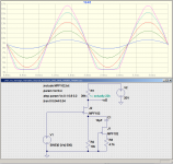
My idea was to use the channel resistance of one JFET as a nonlinear source resistance for a second JFET wired as a common-source amplifying stage. The initial idea was to have everything DC coupled, and this circuit simulated well on LTSpice, but behaved like a class C stage on the breadboard. Not what I was after.
AC coupling the nonlinear resistor (JFET channel) so as to bypass a fixed source resistor did work, though. The circuit produces clean amplification for small input signals, then begins to smoothly round off negative half-cycles when driven harder.
I put together an input JFET gain stage on the breadboard as before (see post #33 of this thread, 10k source resistor, 47k drain resistor). The output of that first stage was AC coupled to the nonlinear twin-JFET circuit in the attached schematic, and that in turn fed the class D power amp module.
With the same twin-humbucker guitar plugged in as before, clean tones were available with the volume knob on the guitar turned slightly down, moving into a slight growl with the guitar turned fully up. With cap values not optimized yet, the growl was on the muddy side. But there was no harshness to it, so I think it holds promise for a little subtle overdrive.
I also tried switching the JFET in parallel with the fixed resistor (J1) completely out of circuit, leaving me with just two cascaded JFET gain stages, both with unbypassed 10k source resistors. This produced clean tone at all guitar volume settings, but it was a warm clean, without the harshness I usually hear from an accurate op-amp stage.
If I may borrow mjd_tech's word one more time, I still have not managed to get "gling" out of my JFETs. But at least I got some usable growl.
I have another mad circuit idea in my head now in the ongoing (and so far, futile) quest for JFET "gling". I'll see if I can get that idea onto a breadboard soon.
Meantime, here's the circuit that I've been talking about in this post. It may be worth wiring an SPST switch in series with J1's drain, so the additional nonlinearity can be switched in or out at will.
Oh yeah, for the particular MPF102 I used for J2, it was necessary to use a 22k drain resistor to get the drain to bias up to about 9 V DC (running on 17.7 V DC from two 9V batteries in series). LTSpice thinks 39k is the proper value to use. JFET parameter spreads strike again.
One final point, the "de-nastification filter" was not used today at all. I figure there's no point until I finish the new ported cab, and know exactly what the whole thing sounds like.
So far my ears are telling me that even one JFET gain stage in the preamp signal chain considerably reduces the amount of nastiness I hear. I still don't know exactly why, but my working hypothesis is that the JFET nonlinearity is doing something to squash the big initial transient at the start of each picked guitar note.
-Gnobuddy
Attachments
This TI "guitar preamp" is remarkably dubious.
The schematic is shown in the user guide downloadable in the link I gave in my previous post. I got it as a point of reference. I thought that those cool looking knobs were worth half the price, but it didn't come with any knobs.
Low input Z, very low when gain is maxed.
In "clean" mode the guitar sees a BJT emitter follower with a 10K emitter load, and 1100 ohms into the opamps virtual ground. The input impedance will be roughly beta times 1K ohms, which isn't far from that of some popular guitar amps. I figure that I'll hack up that PCB, and maybe start by sticking a fet in that first stage, but I'll play through it as is first.
I agree that it will probably sound nothing like what I have been playing for 50 some years, and possibly suck big time, but I will hold my judgment until I actually plug it in.
My guess is that it will sound similar to the kid who lived next door to me in Florida's "practice amp," only lots louder. He had a little Peavey that he brought me twice to fix. It had a couple of opamps driving an 8 watt chip amp (which was blown). On the second repair I got a 20 watt chip amp from the National sales engineer that had the same pinout, but would live forever on the 15 volt power supply in the Peavey regardless of what the kid did with the speaker leads.....He played in a death metal band, and often used that little turd cranked to 11 and miked up through the PA. Yeah, he became an electrical engineer and wound up working in the same plant I did for a year of so. Then the layoffs happened.
Ah, well. Yet another audio engineer who didn't get the memo about guitar amps being very different...
I think most folks who spend the time to become proficient on e-guitar will not also have the time to become an EE who can get hired at Big Company.
...kid who lived next door to me ... played in a death metal band.... Yeah, he became an electrical engineer and wound up working in the same plant I did.....
Well, there goes that theory.
I do know a guy with very solid Hi-Fi cred hired at TI, first as support engineer then moved to hi-fi audio (basically digital, but working to be "better" than all the small-companies' digital audio chips).
... isn't far from that of some popular guitar amps. ....
True. But this is now (checking) the 21st Century! Wheezy Germanium parts have gone out of style (AND back in style again, but as "spice"). Aside from the EF being worked semi-hard (not hard enough to put real roundness on string-tone), TI _sells_ some very fine FET input opamps which would take the good Noise Figure down another whole dB.
And there is an inverter in there which seems to do nothing? (Sells a half-chip, I guess.) Like Absolute Phase matters, when all pickups and speakers are phased randomly.
Oh, sure, I have seen far worse even on "decent" amps.
who spend the time to become proficient on e-guitar will not also have the time to become an EE
I did that as well, but went about it in a most out of the ordinary way.
Lets start with about 10 years (off and on) of guitar lessons courtesy of my parents, plus playing in a garage band at age 13, which formed because of a random discussion at a Boy Scouts meeting of all places. The band broke up 2 years later because the forced integration of the school system in the 60's had us going to 3 different high schools even though we could walk to each other's houses.
I thought that I was a good guitar player until a friend convinced me to go with him to a Monkee's concert. Why? Because the opening act was supposed to be an awesome guitar player......UH, the opening act was Jimi Hendrix. After seeing that show, I knew that I was NOT a good guitar player, and never would be. I kept playing though.
I wound up becoming an engineer by a equally unusual path. I answered a "technicians wanted" ad in the Miami newspaper after the usual "worthless teenager" argument with my father, and got hired to tune HT-220 walkie talkies as they came off the assembly line. I then spent 10 years in the test equipment cal lab fixing things and making cool stuff in my spare time.
Some of my cool stuff had caught the attention of the engineering groups, but it was actually a "Camaro" belt buckle that got me hired into engineering. The buckle led to an "interview" that consisted mainly of questions about 67, 68 and 69 Camaros, and the fact that I had parts the hiring person wanted......Poof, instantly I'm an engineer! Then, after I proved that I could design radio circuits, they sent me to school to get two engineering degrees.....and paid for it!
Wheezy Germanium parts have gone out of style
As a kid building things out of stuff obtained from other peoples trash, much of my early stuff used tubes. Then I discovered those big round transistors on the back of some car radios (2N174). I made some loud amps with those, but they blew up far easier than a tube. I made some cool fuzz boxes with germanium transistors pulled out of old radios too. I may be known for blowing up tubes, but I have fried far more semiconductors in my lifetime than tubes.
I got an email from the TI engineer who was responsible for the EVM shortly after receiving it, asking what I thought of it. I had put a link to my web site on the EVB order form (they asked for it). I'm guessing he knew that I at least played guitar, and he understood a little bit about tubes, but thought most of my stuff "worked in class A". I had to reply that I probably wouldn't hook it up till next year......I guess it's almost next year.
Probably true, but there are always outliers, and I think this is exactly the sort of thread where you will find some of them.I think most folks who spend the time to become proficient on e-guitar will not also have the time to become an EE who can get hired at Big Company.
I was a late starter with music through force of circumstance, and I only started teaching myself to play the guitar while working on my Bachelor's degree. When the pressure really came on a few years later in grad school, I stopped playing the guitar for a number of years, but once I was out of school and settled into my first job, the guitar eventually called me back to it.
I didn't get an EE in college - I went in a different direction. But I spent more than enough years in college to have become an EE if that had been the goal.
I began teaching myself electronics at about age eight or nine, long before I ever took up the guitar, or got to college. I knew a fair bit about audio electronics by the time I finally picked up an electric guitar - but I still had no idea how to make a good electric guitar amplifier. I made lots of them, they all sounded awful, and I never managed to figure out why.
In fact, it was another twenty years before I tried my first valve guitar amp, and finally began to realize that that "good" amplifiers are bad for electric guitar, and a very specific type of "bad" amplifier is needed to sound really good!
I still haven't figured out how to make the right kind of "bad" amplifier out of solid state devices, which is why this thread exists.
On the plus side, I would say I now know how to make an "okay" solid state electric guitar amp. But so far, nothing that sounds as good as even my hybrid Super Champ XD.
As for the guitar, I am still learning, and still improving, slowly. Often improvements come in the form of being able to play the same thing as before, while becoming able to free up a little of your brain to do something else at the same time - for example, being able to sing harmony (instead of the main melody) while playing rhythm, or, some years later, being able to sing the melody and play lead guitar at the same time, and so on.
IMO getting good at guitar is definitely a lifetime task. Its amazing to me that some people get so good at it before they're out of their teens.
As for Hendrix - was he a great guitarist, or a great showman, with a knack for appealing to people who were looking for excitement more than they were looking for music?
-Gnobuddy
Progress on the project has been slow of late, I get home from work too late and too tired to do anything in the wood shop, and the final refinement of the electronics has to wait until the speakers are installed in their new cabinet, and I know how they sound there.
I did manage to spray-paint the front baffle black so it doesn't show through whatever material I end up using for the speaker grille.
Other than that, the only progress I have to show is the circuit idea I came up with. A screenshot of the LTSpice simulation is attached.
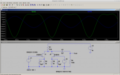
The idea is to parallel two JFETs, bias them to equal quiescent currents, and then drive the two gates with equal amplitude, opposite phase signals. Which sounds like lunacy, because if JFETs were linear, this would cause the AC component of the two drain currents to cancel each other.
However, JFETs are not linear. There is also a quadratic component, and the square of (x) has the same sign as the square of (-x). This means that any second harmonic component in the individual drain currents will be in phase, and will add up rather than cancel. Meantime, the components at the fundamental frequency will have opposite phases, and will cancel.
The same cancellation/ addition idea should apply to other odd and even harmonics - all odd harmonics will cancel out, all even harmonics will add up.
Basically, it's the opposite of the push-pull output stage design we all know well. I think a good name for this circuit would be "push-push".
The concept seems to work in LTSpice - you get a frequency doubled output (and gain below unity) if both inputs are equal amplitude.
For guitar purposes I don't want the fundamental to cancel out, rather, I just want to be able to enhance the amount of second (and other even order) harmonic distortion. Which should be easy to do simply by dialing one of the two antiphase signals down in amplitude.
Something like a cathodyne ("sourceodyne?") can provide the two antiphase signals, of course.
I'm attaching the LTSpice simulation file (.asc) as well as the screenshot, in case anyone else wants to tinker with the circuit.
Will this circuit finally bring the ever-elusive "gling" to an entirely solid-state preamp? Or fail like all my previous attempts? I guess I'll find out soon!
-Gnobuddy
I did manage to spray-paint the front baffle black so it doesn't show through whatever material I end up using for the speaker grille.
Other than that, the only progress I have to show is the circuit idea I came up with. A screenshot of the LTSpice simulation is attached.
The idea is to parallel two JFETs, bias them to equal quiescent currents, and then drive the two gates with equal amplitude, opposite phase signals. Which sounds like lunacy, because if JFETs were linear, this would cause the AC component of the two drain currents to cancel each other.
However, JFETs are not linear. There is also a quadratic component, and the square of (x) has the same sign as the square of (-x). This means that any second harmonic component in the individual drain currents will be in phase, and will add up rather than cancel. Meantime, the components at the fundamental frequency will have opposite phases, and will cancel.
The same cancellation/ addition idea should apply to other odd and even harmonics - all odd harmonics will cancel out, all even harmonics will add up.
Basically, it's the opposite of the push-pull output stage design we all know well. I think a good name for this circuit would be "push-push".
The concept seems to work in LTSpice - you get a frequency doubled output (and gain below unity) if both inputs are equal amplitude.
For guitar purposes I don't want the fundamental to cancel out, rather, I just want to be able to enhance the amount of second (and other even order) harmonic distortion. Which should be easy to do simply by dialing one of the two antiphase signals down in amplitude.
Something like a cathodyne ("sourceodyne?") can provide the two antiphase signals, of course.
I'm attaching the LTSpice simulation file (.asc) as well as the screenshot, in case anyone else wants to tinker with the circuit.
Will this circuit finally bring the ever-elusive "gling" to an entirely solid-state preamp? Or fail like all my previous attempts? I guess I'll find out soon!
-Gnobuddy
Attachments
Here's a couple of articles regarding tube emulation with fets.
I believe these are prior to KMG's work, and he built on these ideas.
I don't remember where they came from, I forgot I even had these.
These are translated from Russian, some things come out kind of strange.
Also they use some funky Russian Jfets.
The "Kemph" article has a lot of equations, which I do not understand.
It explores the idea of a diode from gate to a split source resistor.
The "oldmike" article improves upon the "kemph" idea and introduces the negative supply.
Hopefully you will be able to extract and read these, they are htm files with graphics embedded in base64 format. Works for me on Firefox/Ubuntu.
Attachments
Thank you! It's interesting to see some of the lead-up to KMG's eventual work.Here's a couple of articles regarding tube emulation with fets.
No problems at all, using Xubuntu 16.04 and Firefox.Hopefully you will be able to extract and read these
One of the things I'm still unclear on is how deep into overdrive you have to go before KMGs and related work becomes relevant. Does all this matter for blackface Fender clean tone territory, I wonder?
I guess I am going to have to find out in a hurry. Time is really running out now. I have to work all of this week, so I won't really have much free time until Saturday, and then Christmas will be so close that there will inevitably be other chores and responsibilities.
But, whether or not I make the Dec 25 deadline, the project will be completed, and gifted to my friend. Worst case, it will be a slightly delayed Christmas present.
I did make a little progress today. I finally made it back home early enough to drag myself to the wood-shop and make a little more sawdust. I used the router and round-over bit to clean up all the edges of the speaker enclosure. I guess the next step is to glue in the front and back baffles, then hand-sand and varnish.
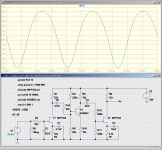
On the preamp electronics front, the easiest next thing to try is bypassing the source resistors in the two JFETs (the one in the input stage, and the one in the de-nastifying filter.) If I put the (inverting) tone control in between, that will encourage even harmonic distortion (the 2nd JFET will be driven by a waveform that has taller positive-going half cycles, encouraging it to produce even taller negative-going half cycles.)
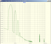
I tested the concept quickly in LTSpice today (using a generic BJT phase inverter because I did this during my lunch break at work, and didn't have my tone control schematic handy). It looks like maybe 10% 2nd harmonic distortion can be coaxed out of the circuit just before it clips, and that should be enough to produce some audible effects. The waveform is not unlike what I got from a small-signal pentode (6AG5) during some earlier guitar preamp experiments, and that preamp had very nice shimmery clean tones.
The 3rd harmonic is still a full 40 dB down in the simulation, probably too low to be audible in a guitar amp. I don't know how close to reality the simulation is, though.
-Gnobuddy
Attachments
Here's a couple of articles regarding tube emulation with fets.
I believe these are prior to KMG's work, and he built on these ideas.
<snip>
A while back I tried to find the source material and in the end gave up. Nice to see it is still around. Took a while to get through the translation. Would really like to play with the ideas but I have a tube amp to build instead. Might even be as challenging.
There are always challenges with every design and build, and I am sure you are dealing with plenty of them. Good luck with the build, and I hope you will share some of it with us eventually. (Is there another thread already?)I have a tube amp to build instead. Might even be as challenging.
Still - in the preface to Merlin Blencowe's "Designing Valve Preamps for Guitar and Bass, Second Edition", he writes "...valves seem to produce good tone almost innately and effortlessly, with the simplest of circuits." And I think he is right about that!
And IMO when we're talking about solid-body electric guitar amplification, the rest of the story seems to be that JFET and MOSFET circuits might, with considerable effort, sound decent, while BJT circuits will pretty much always sound bad...
I think partly we can blame the design of the traditional electric guitar pickup, which was originally designed and evolved to work best with triode valves. Piezo pickups and low-output, low-impedance magnetic pickups like the Shadow Nanomag work fine with solid-state circuits, but don't produce the sounds we expect from solid-body electric guitars.
I have the feeling that there are some interesting and significant ideas floating around just under the surface of this thread, thanks to all the good input (including very interesting links) we've seen here.
For instance: I read a paper, complete with careful experimental data, that showed that most small signal triode valves in fact closely follow a square-law transfer function (for Vgk v.s. Ia), and not the famous Child-Langmuir "three-halves law".
We know that JFETs follow a square law transfer function too, and quite accurately at that. Which means small-signal vacuum triodes and JFETs are both square law devices.
So it should be easy to get JFETs to sound exactly like triode valves...but it isn't!
So it turns out that the things we guitar players like about vacuum triode amplification don't have all that much to do with the three-halves law. They do have something to do with a square law transfer function (JFETs sound more "valvey" or "tubey" than BJTs.) But JFETs still don't sound quite as good as good as an excellent vacuum triode valve...so there is something important out there that goes beyond the square law.
What might that be? Is it really the grid current flow that KMG et al worked so hard to capture? Does grid current flow matter that much even for what we call "clean tone"?
I have suspected that grid current flow even in the input stage of a guitar preamp might have something to do with softening guitar pick attack transients (I mentioned this in post #3 of this thread, back on page 1). Maybe KMGs work shows that this really is so?
A pre-recorded guitar signal (looper pedal) running simultaneously into both an accurate op-amp gain stage and a typical triode valve gain stage, with both outputs fed to an oscilloscope, should tell a lot. Match the two voltage gains with a gain pot at the output of the triode valve, maybe even put the 'scope into channel difference (A-B) mode, so one can see what, if any, nonlinear stuff is happening in the triode stage.
I think I have most of the stuff I'd need to do the experiment. But there are so many projects already in the queue!
For the immediate future, at least, I have to stay focused on finishing this amp as quickly as I can.
-Gnobuddy
- Status
- This old topic is closed. If you want to reopen this topic, contact a moderator using the "Report Post" button.
- Home
- Live Sound
- Instruments and Amps
- Tube Emulation & EQ