Ok so i came up with this idea to learn about valves and tubes...
i Buy a simple tube print from china and i modificate it to hook up my electric quitar to the home stereo CD / LINE input...amplifier...
Wy? Just to get an idea what a tube does and what it sounds like.
Now i bought just like more people the 6J1 tubes. Since the print is stereo and the quitar mono i thought i should hook up the output from one tube to the input of the next.
But offcourse it doesn't quite work.
One question extra is wy in these desigs isn't the -26 the "ground".
So input tube and outputs all share the same ground (its my gut feeling that its not right, but don't have the theory to confirm this).
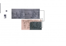
I have made this drawing can anybody please help and tell me what i'm doing wrong?
i Buy a simple tube print from china and i modificate it to hook up my electric quitar to the home stereo CD / LINE input...amplifier...
Wy? Just to get an idea what a tube does and what it sounds like.
Now i bought just like more people the 6J1 tubes. Since the print is stereo and the quitar mono i thought i should hook up the output from one tube to the input of the next.
But offcourse it doesn't quite work.
One question extra is wy in these desigs isn't the -26 the "ground".
So input tube and outputs all share the same ground (its my gut feeling that its not right, but don't have the theory to confirm this).
I have made this drawing can anybody please help and tell me what i'm doing wrong?
Attachments
 Moved to Instrument & Amps forum per forum policy which is where guitar amp gurus all hang out..
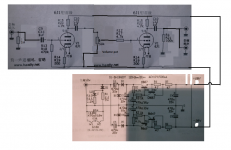
.....it doesn't quite work.....
What does that mean? Silence? Smoke? Explosion? Won't dig a ditch?
The schematic, as drawn, with the odd grounding, should work. It may distort. It may buzz or pick radio signals, especially if not in a metal box. Offsetting "ground" 26V is unusual, I might even say un-natural, but does simplify some other details. The input, output, and power supply caps keep it all together for signal.
Vacuum tubes tend to like a lot of voltage. Since the existing power amp used +26 and -26 vol supplies, by using -26 as ground for the preamp allows the designer to use the already existing 52v supply (split into the two 26v rails) across the tubes. If they used earth as "ground, then they either would have to run the tubes on 26v or add a second power supply.
A simple guitar amp with tubes would be the time honored Fender Champ amp. A simple basic amp, but there have been a million of them made, the parts are all readily available, and documentation also out there for free.
A simple guitar amp with tubes would be the time honored Fender Champ amp. A simple basic amp, but there have been a million of them made, the parts are all readily available, and documentation also out there for free.
...use the already existing 52v supply (split into the two 26v rails) across the tubes. ....
It appears to start with 12V AC. This rectified to ~~12V DC for heater. Also *two* voltage-doublers to make two ~~30V DC raw rails, smoothed to +/-26V final supplies. All wired common.
Seems to me that a voltage-Quadrupler can work the same. Jack up to +60V DC, smooth to 52V DC, comes out the same and is much less confusing to old tube heads like me. Given proper design, the sag is the same either way. However proper design of a Quadrupler is more work (or rather: fewer ready to steal examples out there).
Another argument is that, some places, 25V is considered safe to touch (so 26V is hardly a danger). The +/-26V scheme leaves the whole circuit "touchable" relative to system common. Of course this is arbitrary and situational: 48V is used in phones and Phantom microphones because the danger is very slight and only trained technicians usually handle those screws. Tommy Edison used 100V because it seemed safer to him. Some folks are afraid to lick a 9V battery. Tastes differ.
Firsts thanks for the input/reactions its nice to have people with knowledge think allong.
Second: you wrote...
Okey well if the schematic is right i have to check the chinese PCB")
or perhaps a value of a component is way off or i lost a tube??
Both emit light at the bottom, but only one of them allot on top, the other more like dimm/off.. (when i swapped them it stayed the same so no clue yet)...
When i try it i need to open up the amplifier (of the stereo) to start to hear some buzz and when i then hit the low E string (lowest tone), i feel through the buzz sound that the cone moves differently but there is no bass sound or something like that...(hence i needed to feel). I bet that only on the LOW E it kinda moves high e is a no go...
Now that i think of it it looks like the "speed" is not there.... and that it doesn't amplify allot. (not enough hence i need to open up the stereo allot).
Since i do have a scope, USB PC one, i could hook it up and test the signals between the 2 stages??? But what kind of test signal do i put in?
Music?
But honestly i smiled this morning when you told me that it should work...
albeit it will probably mean that some values are way of then?
Second: you wrote...
What does that mean? Silence? Smoke? Explosion? Won't dig a ditch?
The schematic, as drawn, with the odd grounding, should work. It may distort. It may buzz or pick radio signals, especially if not in a metal box. Offsetting "ground" 26V is unusual, I might even say un-natural, but does simplify some other details.
The input, output, and power supply caps keep it all together for signal.
Okey well if the schematic is right i have to check the chinese PCB
or perhaps a value of a component is way off or i lost a tube??
Both emit light at the bottom, but only one of them allot on top, the other more like dimm/off.. (when i swapped them it stayed the same so no clue yet)...
When i try it i need to open up the amplifier (of the stereo) to start to hear some buzz and when i then hit the low E string (lowest tone), i feel through the buzz sound that the cone moves differently but there is no bass sound or something like that...(hence i needed to feel). I bet that only on the LOW E it kinda moves high e is a no go...
Now that i think of it it looks like the "speed" is not there.... and that it doesn't amplify allot. (not enough hence i need to open up the stereo allot).
Since i do have a scope, USB PC one, i could hook it up and test the signals between the 2 stages??? But what kind of test signal do i put in?
Music?
But honestly i smiled this morning when you told me that it should work...
albeit it will probably mean that some values are way of then?
And a general tip. Get one stage working before you add another stage. I would start with just the power supply, part of the power supply, and verify proper voltage. Build the amp step by step, testing all the way. (You need a voltmeter; electricity is invisible.)
The thing is that the print came out of the box so needed to mod the design in situ.
Saying that it was not to difficult. I cut of a leg of the output RCA's and joined them at the back (so i get a double output for the amp.).
I then joined the disabled output to the input of the next stage (piece of wire).
I modded the 50K so only one input is trimmed etc. etc..
Quite a doable/nice mod if it would work
.What i did was almost that...i first checked all voltages where right then i added the tubes and started with input signals from the guitar.
I will disconnect one tube and check what i can measure with my scope...
I could be wrong, but I suspect changing the PS to a quadrupler is beyond the OPs level.
Well i don't think so. Saying that i'm not a electronics engineer i am a control engineer (industrial automation).
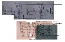
Is the attachment something wat could work?
Attachments

It works!!
It sounds very natural!
What i did was i disconnected the infeed of the next tube, like you suggested, before the volume pot. and connected an 50K resistor to ground.
Now i can just play like if its my normal amp on natural position.
i have put the stereo amp in direct mode (no loudness).
And it works like a charm
i was sow happy i almost recorded a video.(what kept me from doing it is that my next thing to improve is my playing and not my amp
(only playing since 3months now)).What i did notice (i checked both tubes) is that one sounds quite different then the other so perhaps i damaged one or its a worse one its not as bright lid up when looking through the top ...(swapped positions to compare).
Next question is what is wise to?
Do i even need that extra tube???
If i open the amp to much i start hearing buzz.
Playing with the tone knob on my quitar i can eliminate it, but offcourse that influences the tone (increasing tone means more buzz).
If i enable loudness on the amp i introduce quite some noise back.
Whats the next advice ?
Can we take out (filter) the buzz from the first stage and introduce that into the next?
Or should i lower the gain on the first stage (so i don't amplify the buzz) and feed that into the next tube for the power?? (i probably loose "signal" then too right??
Very happy guys with this
Both the 6J1 and 6AK5 are pentodes, yet the schematic Tkswdr posted shows triodes.The tubes are a Chinese built Russian version of the 6AK5 from what I am lead to believe.
Are the pentodes triode-connected for use in this circuit? It would be nice if the schematic actually showed that.
-Gnobuddy
Note the 5/6 mark at the "plate". I believe these are Plate and Screen for 6J1 (~6AK5). So yes, triode. Mu near 20?
That 6J1 shows in a LOT of low-cost Asian "tube buffers". It must have been the all-purpose RF/IF tube for them (as 6AK5 was for high-class US radio), and warehoused in huge quantity.
That 6J1 shows in a LOT of low-cost Asian "tube buffers". It must have been the all-purpose RF/IF tube for them (as 6AK5 was for high-class US radio), and warehoused in huge quantity.
- Status
- This old topic is closed. If you want to reopen this topic, contact a moderator using the "Report Post" button.
- Home
- Live Sound
- Instruments and Amps
- DIY Guitar amp