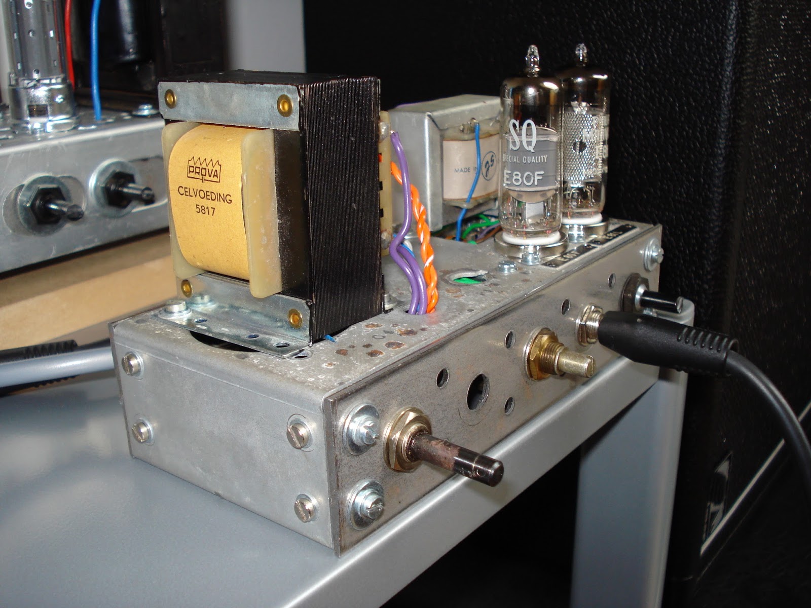
Yes, they are. The first chassis was from a radio, the second from (i believe) an ancient fax machine. It had little nameplates ("E80F" and "E81L") at the openings for the two tubes so I made a little amp (a whopping 2 Watts) with it.
Some more pictures here: OTL800: Gitaarversterker met EF86 + 2 x ECL86 push-pull afgerond and OTL800: Tussendoorproject: Gitaarversterkertje met E80F en E81L afgerond
Some more pictures here: OTL800: Gitaarversterker met EF86 + 2 x ECL86 push-pull afgerond and OTL800: Tussendoorproject: Gitaarversterkertje met E80F en E81L afgerond
Those tubes don't look so expensive as the EF86 or the ECL86.
Yeah. I wanted to ask how does ECL86 compare to other tubes by sound. Built an ECL86 amp bout' year ago and it did not turn well for me, sound was just too brittle for me.
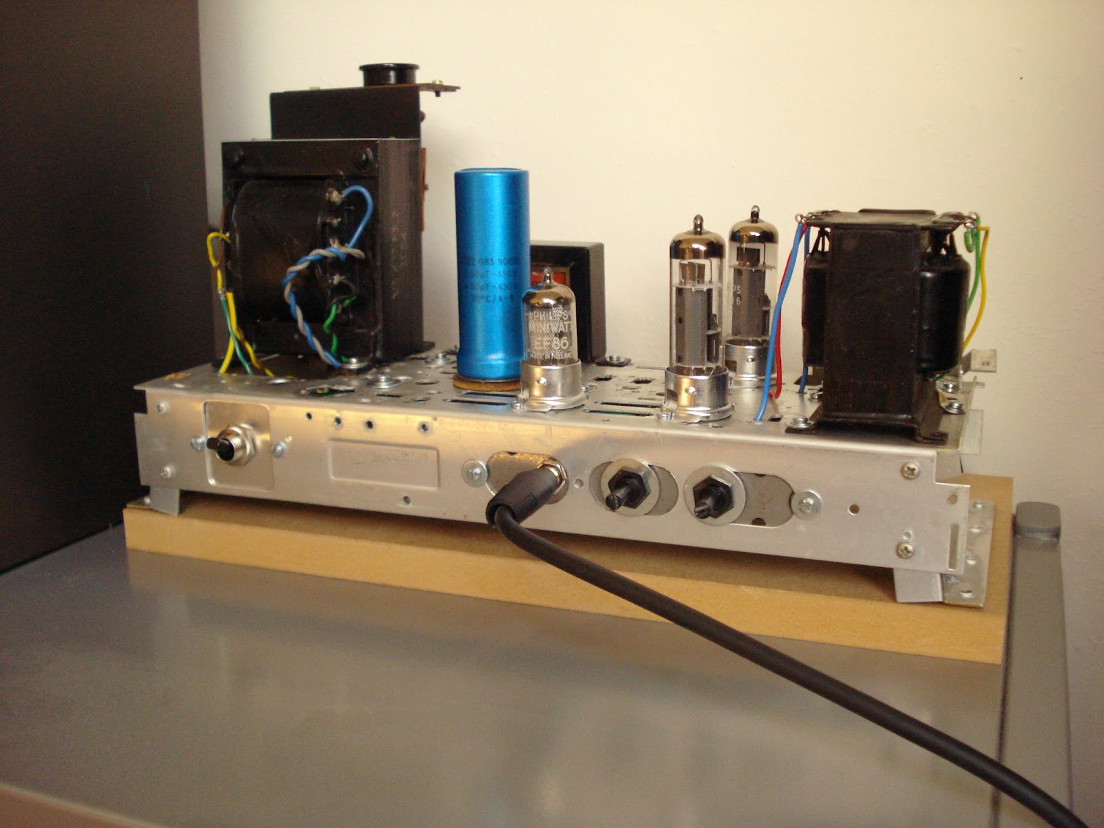
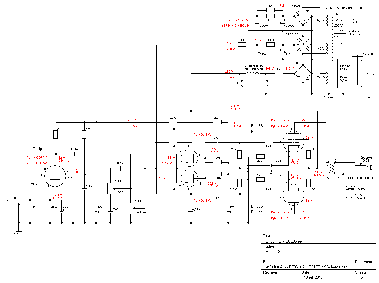
The amp with 2 x ECL86 sounds quite brittle, but I kind of like that. The schematic is heavily based on the bright-channel of the Vox AC15. The most important differences: A much better quality OPT (from the early 60's and intended for HiFi), a prolonged tail of the phase splitter and a one knob tone control instead of a brightswitch. It has no hum at all and just a tiny bit of hiss. The gain is very high so in hindsight I maybe should have designed it with a tone control with higher insertion loss.
Looking at the datasheets the ECL86 comes close to the EL84, but then with max 9 Watts anode dissipation instead of max 12 Watts for the EL84. But the ECL86 is a beam power tetrode while the EL84 is (originaly) a power pentode. The triode in the ECL86 is half an 12AX7 (= ECC83).
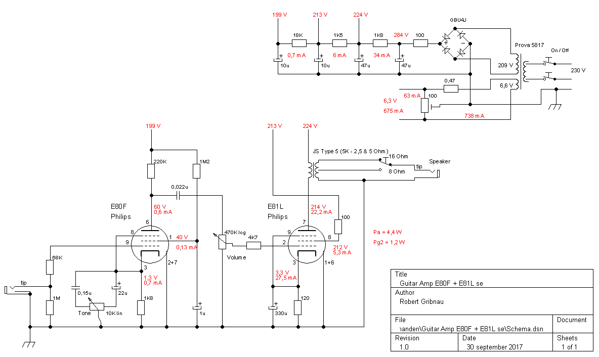
The E81L costs about 7 Dollar NOS in the Netherlands. It was a working horse for the PTT (the former post/telephone/communications service in the Netherlands). It could do both RF signal amplification and (a little...) AF power amplification.
The E80F is considered by some to be an improved EF86 (wich is not quite right because the E80F predates the EF86 by about 4 years) and because of that costs about 25 Dollar NOS overhere. They have the same pinout but the E80F takes 300 mA for the filament against 200 mA for the EF86. In pentode-mode they behave similar but they differ in triode mode (EF86: mu = 38 against E80F: mu = 25).
I will record some soundsamples soon and post them here.
Looking at the datasheets the ECL86 comes close to the EL84, but then with max 9 Watts anode dissipation instead of max 12 Watts for the EL84. But the ECL86 is a beam power tetrode while the EL84 is (originaly) a power pentode. The triode in the ECL86 is half an 12AX7 (= ECC83).
The E81L costs about 7 Dollar NOS in the Netherlands. It was a working horse for the PTT (the former post/telephone/communications service in the Netherlands). It could do both RF signal amplification and (a little...) AF power amplification.
The E80F is considered by some to be an improved EF86 (wich is not quite right because the E80F predates the EF86 by about 4 years) and because of that costs about 25 Dollar NOS overhere. They have the same pinout but the E80F takes 300 mA for the filament against 200 mA for the EF86. In pentode-mode they behave similar but they differ in triode mode (EF86: mu = 38 against E80F: mu = 25).
I will record some soundsamples soon and post them here.
I wanted to build the second amp with parts i allready owned (i have bought way too much electronic stuff allready) and succeeded in that except for the power cord. Because of the limited space between the tubeholders and the front of the chassis, in combination with the available potmeters, made me choose for a tone control in the cathode lead. I did not want longer connections to and from a tone control between the E80F and the E81L because of the high impedance (higher chance on noise/hum problems). I looked on internet for a usable schematic. There are many examples with a two ore more pole switch with one or more capacitors but i did not find one with a potmeter. So i made this one up. It does work (turning from 22uF towards 0,15uF makes the bass a little lesser) but not so impressive as i hoped. Maybe the effect will be a bit better with the 0,15uF replaced by a lower value and/or a higher value for the potmeter.
"One could probably use the EF183 in place of the E80F."
Hello Thomasha. The EF183 is a remote cutoff pentode. Allthough the guitar signal at the first stage is not so high, i think there still will be more distortion with a remote cutoff pentode than with a sharp cutoff pentode.
But maybe some more distortion is a good thing for a guitar amp.
Hello Thomasha. The EF183 is a remote cutoff pentode. Allthough the guitar signal at the first stage is not so high, i think there still will be more distortion with a remote cutoff pentode than with a sharp cutoff pentode.
But maybe some more distortion is a good thing for a guitar amp.
- Status
- This old topic is closed. If you want to reopen this topic, contact a moderator using the "Report Post" button.
- Home
- Live Sound
- Instruments and Amps
- Two diy guitar amps