Hi, I’m trying to restore an old Fender Studio Bass combo amplifier.
I’ve used it for no more than one or two hundred hours in early 80’s and since then it rested in the basement.
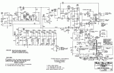
The amplifier is equipped with six 6L6GC (still the original Fender tubes); nominal output power is 180W.
Original schematic reports 500V anode voltage and –61V control grid bias, so I supposed a very small idle anode current, very close to class B.
I replaced all the electrolytics with new capacitors (F&T), measured all the resistors in the power stage and inserted a 1 ohm resistor between each 6L6GC cathode and ground.
After switching on, I measured the following values:
anode voltage: 525Vdc
control grid voltage: -63Vdc
heater voltage: 6.8Vac
cathode current:
6L6GC #1: 77 mA (red plate after few minutes!)
6L6 GC #2: 48 mA
6L6 GC #3: 38 mA
6L6 GC #4: 41 mA
6L6 GC #5: 37 mA
6L6 GC #6: 33 mA
(voltage higher than those reported on the schematic can be explained considering that the mains power voltage was between 228 and 230 Vac, and the amplifier has been designed for a 220 Vac mains voltage).
Screen grid currents were between 1.6 and 1.9 mA, except for 6L6GC #1, that had 2.7 mA.
I removed 6L6GC #1 and 6L6GC #2 and using the remaining four 6L6GC, I applied a 1KHz sine to the amplifier input; maximum out power (before clipping) was 115W (on a 8 ohm load); distortion at 100W output power was less than 2.5%, not so bad, considering the four power tubes were working with a mismatched load.
So, let’s start with the questions:
- tubes V1A and V3 in the preamplifier have a 750uF cathode bypass capacitor, is this huge value really necessary? (never seen in other Fender amplifiers)
- I can easily lower the heater voltage using a simple resistor, but it is more complicated to reduce the anode voltage; considering that the mains voltage in Europe is 230Vac +/-5%, the anode voltage can reach (theoretically) 550Vdc; is it really dangerous for the 6L6GC (old RCA/Fender or the new Russian or Chinese equivalent tubes)?
(IIRC some MusicMan amplifiers use 6L6 tubes with 700V anode voltage)
- why the bias currents are so relatively high, despite the –63Vdc at the control grid? Other Fender amplifiers normally use voltages between –35 and –45 Vdc to obtain the same bias currents; according with the tube data sheet, -63Vdc at the control grid should cause few mA of anode current.
- If I replace only 6L6GC #1 (defective, red plate!) and, maybe, #2 with modern equivalent (JJ or Sovtek or Svetlana) and I keep the other original RCA/Fender, will the new tubes have a comparable bias current (30 – 40mA) with the control grid polarized at -63Vdc?
- I’m planning to introduce a separate bias regulation for each tube, (the separate bias regulation could be useful in case of further/future tube replacement); in order to have a bias current of 33-36 mA in each tube (about 60% of maximum plate dissipation), I need to start from a higher negative voltage, say –70Vdc; can I get the missing 7 volts rising the cathode potential, with a a resistor or a zener diode in the cathode circuit of each 6L6GC?
If yes, which power should have this resistor or zener? (consider that the average cathode current at full output power will be much higher than bias current).
Every answer, comment or suggestion will be appreciated.
I’ve used it for no more than one or two hundred hours in early 80’s and since then it rested in the basement.
The amplifier is equipped with six 6L6GC (still the original Fender tubes); nominal output power is 180W.
Original schematic reports 500V anode voltage and –61V control grid bias, so I supposed a very small idle anode current, very close to class B.
I replaced all the electrolytics with new capacitors (F&T), measured all the resistors in the power stage and inserted a 1 ohm resistor between each 6L6GC cathode and ground.
After switching on, I measured the following values:
anode voltage: 525Vdc
control grid voltage: -63Vdc
heater voltage: 6.8Vac
cathode current:
6L6GC #1: 77 mA (red plate after few minutes!)
6L6 GC #2: 48 mA
6L6 GC #3: 38 mA
6L6 GC #4: 41 mA
6L6 GC #5: 37 mA
6L6 GC #6: 33 mA
(voltage higher than those reported on the schematic can be explained considering that the mains power voltage was between 228 and 230 Vac, and the amplifier has been designed for a 220 Vac mains voltage).
Screen grid currents were between 1.6 and 1.9 mA, except for 6L6GC #1, that had 2.7 mA.
I removed 6L6GC #1 and 6L6GC #2 and using the remaining four 6L6GC, I applied a 1KHz sine to the amplifier input; maximum out power (before clipping) was 115W (on a 8 ohm load); distortion at 100W output power was less than 2.5%, not so bad, considering the four power tubes were working with a mismatched load.
So, let’s start with the questions:
- tubes V1A and V3 in the preamplifier have a 750uF cathode bypass capacitor, is this huge value really necessary? (never seen in other Fender amplifiers)
- I can easily lower the heater voltage using a simple resistor, but it is more complicated to reduce the anode voltage; considering that the mains voltage in Europe is 230Vac +/-5%, the anode voltage can reach (theoretically) 550Vdc; is it really dangerous for the 6L6GC (old RCA/Fender or the new Russian or Chinese equivalent tubes)?
(IIRC some MusicMan amplifiers use 6L6 tubes with 700V anode voltage)
- why the bias currents are so relatively high, despite the –63Vdc at the control grid? Other Fender amplifiers normally use voltages between –35 and –45 Vdc to obtain the same bias currents; according with the tube data sheet, -63Vdc at the control grid should cause few mA of anode current.
- If I replace only 6L6GC #1 (defective, red plate!) and, maybe, #2 with modern equivalent (JJ or Sovtek or Svetlana) and I keep the other original RCA/Fender, will the new tubes have a comparable bias current (30 – 40mA) with the control grid polarized at -63Vdc?
- I’m planning to introduce a separate bias regulation for each tube, (the separate bias regulation could be useful in case of further/future tube replacement); in order to have a bias current of 33-36 mA in each tube (about 60% of maximum plate dissipation), I need to start from a higher negative voltage, say –70Vdc; can I get the missing 7 volts rising the cathode potential, with a a resistor or a zener diode in the cathode circuit of each 6L6GC?
If yes, which power should have this resistor or zener? (consider that the average cathode current at full output power will be much higher than bias current).
Every answer, comment or suggestion will be appreciated.
Attachments
tubes V1A and V3 in the preamplifier have a 750uF cathode bypass capacitor, is this huge value really necessary? (never seen in other Fender amplifiers)
necessary? Who knows. But what would be the point of changing it?
I can easily lower the heater voltage using a simple resistor, but it is more complicated to reduce the anode voltage
Don't bother the heater supply for half a volt. Within 10% is just fine. Likewise the B+, 550 is within 10% of 500v. It no longer does, but in the old days, Fender schematics had a note that all values and voltages were +/-20%.
VOltage isn't what kills tubes, dissipation is.
Tubes vary greatly in their natural current draw. That is why they sell matches ones and why they make bias adjustable. One set of 6L6 might draw really low current, while the next set might draw a lot of current. All without changing the bias voltage. You can't say "-61v ought to" anything.
Any new tube you add to the group might be close or might be far off from the others, there is no way to know ahead of time.
My own opinion of individual bias controls is that it is a pointless overkill. Others may disagree. First consider that Fender never installed matched tubes in amps when they made the amps. MAtched tubes may have the advantage of some hum cancellation, but it is not necessary. None of the power supplies in these amps are regulated. COnsider that your mains voltage jumps around, meaning so will all the operating voltages inside the amp. SO if your mains goes up 5%, then so does your B+ and your bias voltage, and your heater voltage. And be aware that 5% change on 500v is 25v. It would be a holy miracle if all that were to actually track even a little. SO whatever careful half dozen settings you make right now, will be blown out the window tonight at the gig.
These are guitar amps, not space program precision laboratory devices.
I like them a little cooler myself, but the 525v you have and the roughly 40ma per tube puts them all (except the bad tube) right around 21 watts, which is the magic 70% figure so many guys take as gospel. In other words it isn't terribly high.
You won't get any more volts out of the existing bias supply, but I think adding cathode resistors is an unnecessary complication. Just my opinion.
By the way, the one tube? Try moving it to another socket. Does the excess current travel with the tube, or does any tube in that socket overheat? You need to know if the tube is bad or if the socket/circuit has an issue.
Enzo, thank you for your valuable advices.
First thing I did when I saw the 6L6 #1 plate turning red was to move it to another position, but the excess current followed the tube, so I concluded the failure was in the tube, not in the circuit.
I think I’ll buy one or two new tubes as replacement for 6L6 #1 and see what happens.
Maybe I’ll add a single trimmer to set the common bias voltage; I think I can get a higher negative voltage replacing the single diode in the power supply bias section with a diode bridge (half wave to full wave rectifier).
Enzo, thank you for your valuable advices.
First thing I did when I saw the 6L6 #1 plate turning red was to move it to another position, but the excess current followed the tube, so I concluded the failure was in the tube, not in the circuit.
I think I’ll buy one or two new tubes as replacement for 6L6 #1 and see what happens.
Maybe I’ll add a single trimmer to set the common bias voltage; I think I can get a higher negative voltage replacing the single diode in the power supply bias section with a diode bridge (half wave to full wave rectifier).
I had a Simms-Watts 100 watt valve amp that had the same problem.
I just bought a new set of valves for it and it was fine.
Sometimes the coupling capacitors can go faulty and upset the grid voltage and make the tube run hot but given the problem moved with the valve then its the valve that is duff.
Separate bias trim for each tube will need 6 coupling caps in place of the two.
The bias winding is noted as 60V AC. With a low-resistance rectifier -or- a higher resistance load (2.7K is quite low), it should give nearer 80V.
I would suspect you might try six 25K pots and six 22K resistors to give -38V to -78V bias range. This is a 7.8K total load instead of 3K. If that does not come close, reduce 100r to 47r and 220r to 100r.
I note particularly that while 6L6GC is rated 100K max G1 resistance in fix-bias, Fender usually cheated-up to 220K, BUT in this amp they used 33K which is right on-spec for three grids at 100K. And the trim network is only a few K more. Fender felt they had to respect the grid-current problems that govern the 100K/grid rating.
Stepping back: this is a very "bold" amplifier. 60 Watts per pair of 6L6GC?? And more on modern high line voltage. I think it is an SVT (or Fender 300) at lower sale-price. I won't say "cheap", it was a lot of money and would serve well for hundreds of hours. But for HARD use _I_ would want more tube-stuff to support the 180 Watt rating. When I was poor and tubes were readily available, I used a quad of 8417 at 180W out. Now that I know better (and 8417 are all burned up) I would use 6550/KT88 and very preferably six of them. I do not know if the PT can support six of the bigger heaters. (or even if the big bottles fit the case.)
Note the plan says "210/250V 50/60Hz", so your 230V is right in the middle. However the voltages you report make me think 250V was insane.
I am reminded of certain motorcycles of the early 1970s which would run REAL fast and could be burned-up in a year. They would whup a Harley Davidson, but they were all scrapped by 1980 while that H-D is still running OK.
Has your career reached the point that you need a 180 Watt amplifier? To play very large venues without help from PA? Do you have paid roadies to move this beast and the kind of speaker system which would justify/survive such a monster?
I stopped to play bass at the end of 80’s and this is the reason why my Studio Bass has slept in the basement for about 30 years, so I really don’t need it; further more, it weights about 100lbs (it is a combo) and moving it is a nightmare.Has your career reached the point that you need a 180 Watt amplifier?
But I have time, a lot of electronic components and some instrumentation, so I would like to make it working again.
Concerning the circuit, there is a couple of cathode followers between the phase inverter stage and the power stage and this allowed Fender designer to lower the 6L6 grid resistor to 33K.
The bias circuit you described is exactly what I have in mind (with 20K pots instead of 25K and a resistor between the wiper and the most negative end of each pot to prevent wiper detachment)
Just for information, I replaced only two power tubes (with JJ Tesla 6L6GC) and added a single bias adjustment trimmer.
After that, I measured the following bias currents:
V1 20.5 mA V2 33.5 mA V3 31.0 mA
V4 22.8 ma V5 33.0 mA V6 29.8 mA
(V1 and V4 are the new JJ tubes, the others are the old RCA).
I also noticed that the new JJ tubes, despite of the lower bias current, have a transconductance 20-30% higher than the RCA tubes.
Moreover, bias currents change with mains voltage, but the change is not the same for all the tubes (some of the tubes are nearly insensitive, other tubes change their bias current of 20% or more).
Considering this, I supposed the overall performance was not brilliant, so I was surprised when I measured an output power of 170W at clipping, with a THD of 1.8%, and a maximum power of 200W with a THD of 3% (no sign of crossover distortion at the oscilloscope).
And the sound? GREAT!
Anyone have a link to a good explanation of the tonestack (and it's history - some very specific parts there)?And the sound? GREAT!
Anyone have a link to a good explanation of the tonestack (and it's history - some very specific parts there)?
You can find something here:
TMB Tone Stack
and download a tone stack simulator here:
TSC
Grazie, but I wasn't clear with my question. Sorry!You can find something here:
TMB Tone Stack
I meant to ask about the five band "graphic EQ" + presence control after V2 of the 12AU7.
Last edited:
....five band "graphic EQ" + presence control after V2 of the 12AU7.
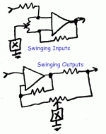
HBfSE calls it a Swinging Output. The specific page may not show, but the book is VERY worth owning.
Swinging Output EQ
It is also in RDH4, I think from an app-note by a choke maker.
Attachments
See alsoI meant to ask about the five band "graphic EQ" + presence control after V2 of the 12AU7.
Equalisers
...
a) What's with the 33K resistor to earth? I have a hunch
I do not know. In-use, it is bypassed by 5uFd, so no effect. A guess: if you have a strong curve dialed-in, then bypass, there will be a considerable difference in overall gain. The 33K leak will tend to reduce the difference, without any large EQ effect.
...
b) where does one get centre-tapped pots?
c) likewise, are the inductors standard of-the-shelf parts?
When you buy a million pots a year, if you need a few hundred "specials", the pot-maker will quote you an OK price on a small batch, just to keep your large business. Likewise audio inductors are almost always "specials", but a large maker can get them.
The CT pots are not essential. They mildly increase hiss. The "no effect" knob setting may not be dead-center. You may not care. If you do, in DIY, you test for the no-EQ point, then set the pot/knob centered there, even if it is really 45%:55% of mechanical rotation.
That was my guess, w'out having all the other component values. ThanksI do not know. In-use, it is bypassed by 5uFd, so no effect. A guess: if you have a strong curve dialed-in, then bypass, there will be a considerable difference in overall gain. The 33K leak will tend to reduce the difference, without any large EQ effect.
Thanks @fulvio and @PRR.
I get most of it. A few questions
a) What's with the 33K resistor to earth? I have a hunch
b) where does one get centre-tapped pots?
c) likewise, are the inductors standard of-the-shelf parts?
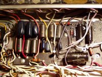
Here is a picture of the Fender equalizer board; inductors are the dark brown parts with coloured dots; they are commercial components, even if they don’t have any manufacturer identification.
The equalizer works, even if it is not very accurate; here are the excursion for the single controls:
80Hz -14 / +8 dB
190Hz -28 / +12 dB
390Hz -15 / +11 dB
1000Hz -30 / +13 dB
1850Hz -30 / +14 dB
If you want to build an equalizer, I suggest to adopt the standard single op-amp schematic; if you can’t find the inductors, you can replace them with “simulated inductors” or gyrators (each simulated inductor is made up with an op-amp and few passive components).
The real issue are the potentiometers; if you use normal linear pots, you get most of attenuation and amplification in the initial and final parts of the pot travel (the same if you use a linear pot as a volume control); one should use pots with special S-shaped (or double log) characteristic: they exist, but are not available to common people; maybe this is the reason why Fender uses the center taped pots (anyway, this could be not a problem with guitar or bass equalizer, as long as you set the pots using your ear, not looking at pot position; many years ago I built an equalizer with inductors and linear pots, and I don’t remember any particular trouble to set it for the right sound).
Attachments
.... inductors, you can replace them with “simulated inductors”....
The plan as-drawn has the inductors floating. This is awkward, at least non-trivial, for simulated inductors.
You are right; I considered to use simulated inductors for a generic op-amp equalizer, not as a replacement for Fender equalizer inductors.The plan as-drawn has the inductors floating. This is awkward, at least non-trivial, for simulated inductors.
- Status
- This old topic is closed. If you want to reopen this topic, contact a moderator using the "Report Post" button.
- Home
- Live Sound
- Instruments and Amps
- Questions about Fender Studio Bass amplifier