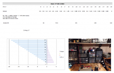
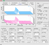
Here is a crude chart. Looks like the control range is just peachy, anode changes more than I thought. The ctl input scaling resistors look like a standard 0-10v could be easily implemented.
Cheers
-
Cheers
-
Attachments
Last edited:
Anode DC shift is about 25 times larger than change in output voltage, that's not very good. I think most single ended vari-mu arrangements will have smaller DC shift.
Yes the patent claims 2v shift so one of my guesses on part value is off , it could be the ef86 but not likely.
But its very useable for my purposes as a limiter stage for classd feed.
I'm lookin around in the Collins schematics now.
Manley has nice write up on replacing the 6ba6.
Manley Tech Pages - Manley Variable Mu<sup>®</sup> Stereo Limiter Compressor
> anode changes more than I thought.
Indeed. Birkemeier's patent says "D. C. level shift at plate (maximum). 2 volts" Your test shows 88V. Here's my old simulation of a triode stage's plate DC change:
Not much different from your test, despite radical different tube and current.
Dunno if your implementation differs from Birkemeier's, or if he was just wrong.
Indeed. Birkemeier's patent says "D. C. level shift at plate (maximum). 2 volts" Your test shows 88V. Here's my old simulation of a triode stage's plate DC change:
Code:
12AU7, 100V, 22K/plate
dBgr   Vplate
  0    34V
  3    64V
  5    74V
 12    89V
 21    95V
26 98VDunno if your implementation differs from Birkemeier's, or if he was just wrong.
Attachments
Ya the sim is close.
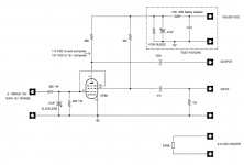
I believe one resistor is not shown on Fig 1 and also one of my resistor values is gross incorrect. The 'gain' is also not matching.
So maybe he was using it in psuedo CC mode. I read about that recently on reverb tank drivers. The patent says "small changes" do not alter plate. Anyway I will spend a little more time digging up a Collins schematic using it.
It definitely is working as a VCA for sure. The only reason not want gross anode shift anyway is for mfg tolerances. I don't have that issue, all of my final designs are fixed adj bias.
> psuedo CC mode.
??
> The patent says "small changes" do not alter plate.
"Figure 2 wherein the family of screen voltage curves are shown as generally curved lines and the dotted line 20 represents a constant output plate current."
> It definitely is working as a VCA for sure.
That's inherent in tubes (in any simple amplifying device). Transconductance is obviously zero at zero current, assumably finite at finite current. Transconductance does not "go away suddenly", it fades off.
> The only reason not want gross anode shift anyway is for mfg tolerances.
No; in audio limiters (patent does mention controlling audio to a transmitter) the attack time for a sudden over-loud signal must be audio rate. As you see, we have part-volt signal with many-volt DC shift due to AGC. Since the attack rate is a low-audio-rate ramp (1mS-50mS), this sudden shift of DC can not be fully filtered-out, "thump".
Even if that low-DC-shift could happen, it implies large DC shift at G2. Which is also the audio input. Such DC shift might upset the stage driving it. If low-Z, then input cap C1 slows response time. However I just saw a way to work that.
Interesting stuff, if you have an example of Collins putting some version into production, I'd be curious to know what it is. At the time the patent was filed, Collins broadcast line was still selling a bridge type limiter, and afterwards moved to a typical 6386 based approach.
Interesting stuff, if you have an example of Collins putting some version into production, I'd be curious to know what it is. At the time the patent was filed, Collins broadcast line was still selling a bridge type limiter, and afterwards moved to a typical 6386 based approach.
I'm looking into the Collins avionics, yes correct the S-line did not use. The nature of the circuit lends itself to AM in a noisy cockpit, using a voice band filter.
Anyway here is a slight update. By changing screen and/or plate load resistor its possible to minimize anode dc change. I played with it this morning and found easy to improve. The down side is distortion goes up slightly- so its a trade-off between anode VDC vs compression and open loop distortion. The distortion still tracking as before. G3 seems to not care much where it is tied.
ANODE DC:
Zero compression = 114 VDC
10:1 compression = 137 VDC
This topology is used in a lot of low voltage B+ automobile radio sets of that time period. Not for compression but to eliminate space charge.
Attachments
> ANODE DC:
> Zero compression = 114 VDC
> 10:1 compression = 137 VDC
Thanks. Something like the claim.
> This topology is used in a lot .... to eliminate space charge
I would dispute "a lot", but whatever.
And while the connection is similar, the Space Charge tubes took G1 to a steady high positive voltage, and didn't have a G3.
I think this thread link solves the mystery of where used.
ARRL article, have to get a copy.
http://www.diyaudio.com/forums/inst...uit-drafting-suppressor-grid.html#post3823489
I still have to go over it in detail, but looks like I should use a remote cutoff pentode to duplicate the patent.
-
ARRL article, have to get a copy.
http://www.diyaudio.com/forums/inst...uit-drafting-suppressor-grid.html#post3823489
I still have to go over it in detail, but looks like I should use a remote cutoff pentode to duplicate the patent.
-
This (Birkemeir) VCA is really astounding to me.
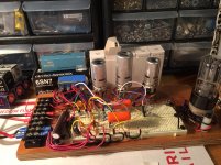
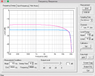
Distortion is now down to 0.15% across a 9:1 range open loop accomplished with resistor/coupling tweek.
Testing again this week with ARRL side-chain.
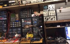
After that will give a try 6SN7 to xfmr PP 600 ohm output stage.
Plugboard in pic is non-standard using a contact strip on every other row.
-
Distortion is now down to 0.15% across a 9:1 range open loop accomplished with resistor/coupling tweek.
Testing again this week with ARRL side-chain.
After that will give a try 6SN7 to xfmr PP 600 ohm output stage.
Plugboard in pic is non-standard using a contact strip on every other row.
-
Attachments
ok now the DC shift from zero compress to max exactly matches patent. 2 VDC max with 150 V supply.
The issue was two things, measuring static DC in/out is not how the circuit works in real time, and the measured dynamic shift is *RMS* signal. next stage blocking does not occur in operation.
The sidechain is not shown but based on what I’m seeing it was similar to the ARRL circuit. not exactly though.
The sidechain is DC and transformer coupled.
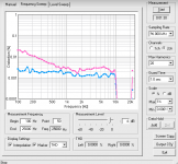
Here is the THD proof, I use a manual distortion meter for initial rough-in then the PC analyzer with Steinberg UR22 as final test. These are the measurements for the circuit operating with zero compression. I'm not sure a EF86 is capable of such low distortion theoretically without NFB. So there must be something going on inside the tube emulating NFB? The gain of the circuit without any compression is X2 (6db). Blue line is the UR22 looking at itself. Magenta is the EF86 circuit. The UR22 hi-z input is used for ef86 channel.
150 VDC, 6.3VDC 6db gain.
150 VDC, 6.3VDC 6db gain.
Attachments
- Status
- This old topic is closed. If you want to reopen this topic, contact a moderator using the "Report Post" button.
- Home
- Live Sound
- Instruments and Amps
- Birkemeier audio compressor