Did you take into account the 14.5 kohm output resistance of BUFREF? (Datasheet page 23.)
No. (shame on me ...
 ) But that Zout just takes the voltage on + terminal of the buffers even further from 2.4V, down to 2.236V.
 Wild guess: maybe during validation they found that the chip works better with a slightly lower common-mode reference, so they added the stupid resistor circuit?
Right, it sounds plausible, but slightly lower than 2.4V or 2.5V? My issue is that either way there are 3 different CM voltages, the internally generated, the driving one, and the trimmed one.
I guess you mean two decades?
Yes Sir! 2 indeed!
")
Unfortunately I can't see any of your pictures on my computer. So far I could look them up in the documents you refer to, but not this one.
Oh, that is too bad! I have tried a bunch of them here, and they open fine. Mind if I ask you to try with another browser, maybe, or even deleting caches related to Imgur: The most awesome images on the Internet
If you still can't see them , I'll upload them again to a different website.
Now it's a bit late here, I'll continue tomorrow. Thanks for the conversation today!
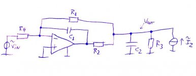
Regarding the calculation of the filter: the first attachment is a model of the filter, made single-ended for simplicity. The component names don't match the datasheet and R3 represents the input resistance of the ADC (or actually one half of it since it is a single-ended model).
One could write out the network equations (assuming ideal components), solve Vout taking Iz = 0 to find the transfer and solve Vout taking Vin = 0 to find the output impedance including the ADC's input impedance.
However, it is clear from inspection that the filter is a second-order low-pass with no (finite) zeros. After all, the order can not be greater than 2 because there are only two reactive elements and the asymptotic roll-off must be second order because when the impedance of either C1 or C2 approaches 0, the response approaches 0. They both go to zero for f going to infinity, so you get a second-order asymptotic roll-off. When the order of the asymptotic roll-off matches the order of the filter, there can't be any (finite) zeros.
Hence, as there are no zeros, to find the shape of the filter response it suffices to find the poles. The poles of the system are the same for any transfer, so it suffices to find the poles of the output impedance including the loading by the ADC. These are automatically also the poles of the input to output transfer.
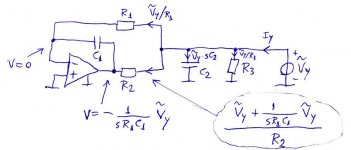
The output impedance is the reciprocal of the output admittance, so the poles of the impedance are the zeros of the admittance. The admittance is easy to calculate, as shown in the second attachment.
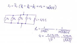
The third attachment shows the result, which is equivalent to an LRC parallel network. The quality factor and natural frequency of such a network are well-known and can be written down straight away.
One could write out the network equations (assuming ideal components), solve Vout taking Iz = 0 to find the transfer and solve Vout taking Vin = 0 to find the output impedance including the ADC's input impedance.
However, it is clear from inspection that the filter is a second-order low-pass with no (finite) zeros. After all, the order can not be greater than 2 because there are only two reactive elements and the asymptotic roll-off must be second order because when the impedance of either C1 or C2 approaches 0, the response approaches 0. They both go to zero for f going to infinity, so you get a second-order asymptotic roll-off. When the order of the asymptotic roll-off matches the order of the filter, there can't be any (finite) zeros.
Hence, as there are no zeros, to find the shape of the filter response it suffices to find the poles. The poles of the system are the same for any transfer, so it suffices to find the poles of the output impedance including the loading by the ADC. These are automatically also the poles of the input to output transfer.
The output impedance is the reciprocal of the output admittance, so the poles of the impedance are the zeros of the admittance. The admittance is easy to calculate, as shown in the second attachment.
The third attachment shows the result, which is equivalent to an LRC parallel network. The quality factor and natural frequency of such a network are well-known and can be written down straight away.
Attachments
It's even weirder on the evaluation kit schematic (page 15), where the 100 ohm is included in the feedback loop around the LM4562 and hence doesn't filter at all, only limits the start-up current and possibly causes instability.
That must be a mistake by Arda! I hope the physical board is not connected as such!
REFPx on pg 16 are 1 pole filtered, same values for R and C, non sense 48 Hz fc, but they are connected ok.

- Status
- This old topic is closed. If you want to reopen this topic, contact a moderator using the "Report Post" button.