Hey, first post - long time dabbler - trying to dive in a little harder to some repairs.
My first real project is this Contessa / Bartell CA 15.
http://bartell.vintageusaguitars.com/files/8412/8292/1460/ContCA15.pdf
It is just the chassis which was removed from the combo amp. Got it free and I've powered it up (tubes glow) but I get no sound.
I was going to fire it up again tonight and poke around in it, but I noticed some odd things which have already stumped me....
The speaker out jack has only the hot lead connected to pin 1 of one of the 6v6s - the ground of the jack is not connected. Shouldnt it be?
When I look up the pin outs for a 6v6 it says pin 1 is unused...
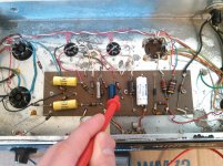
I've attached some pics of the innards - a little push in the right direction would be appreciated!
My first real project is this Contessa / Bartell CA 15.
http://bartell.vintageusaguitars.com/files/8412/8292/1460/ContCA15.pdf
It is just the chassis which was removed from the combo amp. Got it free and I've powered it up (tubes glow) but I get no sound.
I was going to fire it up again tonight and poke around in it, but I noticed some odd things which have already stumped me....
The speaker out jack has only the hot lead connected to pin 1 of one of the 6v6s - the ground of the jack is not connected. Shouldnt it be?
When I look up the pin outs for a 6v6 it says pin 1 is unused...
I've attached some pics of the innards - a little push in the right direction would be appreciated!
Attachments
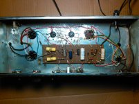

Pin 1 is not used by the tube itself, which leaves it free to use as a convenient solder post. Note your hot speaker lead connects to pin 1 of the lower 6V6, but so does one side of the output transformer secondary, the remaining side of that is grounded just above. The chassis is ground, so the cold side of the speaker jack is thus grounded by the mounting nut.
So the heaters work, fine, now is there high voltage in the circuit, say 300 volts or so?
So the heaters work, fine, now is there high voltage in the circuit, say 300 volts or so?
There are plenty of voltage readings to go by. I always find it best to work backwards, from furthest HT point to first HT point and the same with the signal line.
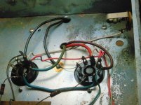
You will be well advised to remove the 0.02uF on the mains as it is affectionately known as the cap of death as they do go short circuit when old and fit 3 core mains cable to earth the chassis.
You will be well advised to remove the 0.02uF on the mains as it is affectionately known as the cap of death as they do go short circuit when old and fit 3 core mains cable to earth the chassis.
I see a two wire power cord and a "death cap." This must go before the cap can live up to its reputation.
Remove the white .02 uF cap at one end of the board, and replace the 2 wire power cord with a three wire cord soldering the green wire to the bare wire going from the chassis ground to where the death cap was.
If that old cap shorts out or becomes leaky it can connect the wall outlet DIRECTLY to your guitar through the chassis ground.
Alrighty! Death cap is out - 3 prong is in - I assume I can run the green wire straight to a transformer bolt? Saw that recommended elsewhere. I need to go get a little wire fastener/eyelet to attach it properly.
Wish I had more time to work on this! Going to fire it up later and hopefully start checking voltages.
Thanks for the tip about the unused tube posts! There are a few places it seems they use them just as convenient solder points - clever, though it was throwing me for a loop!
Wish I had more time to work on this! Going to fire it up later and hopefully start checking voltages.
Thanks for the tip about the unused tube posts! There are a few places it seems they use them just as convenient solder points - clever, though it was throwing me for a loop!
Attachments
> green wire straight to a transformer bolt?
National regulations often want you to go to a "dedicated" chassis screw.
Why? Some day your field service techs have to replace a power transformer. They disconnect the green, forget to re-connect it, unsafe product. So you install a screw that will "never" be removed (except perhaps for cord replacement).
In vintage amplifiers, yes, a transformer bolt is substantial and commonly understood by techs.
Progress is happening!
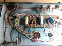
Fired her up and started checking voltages. Got AC 6.3ish on all the tubes - got high voltage on all the tubes except for the first preamp tube. I think I should be seeing it @ pins 1 and 6 (they are jumped together) - the resistor they are connected to should be 220k I believe - though I cant get a reading off it. (most of the other resistors seem okay so far)
On the second 12ax7 pins 1 and 7 are jumped together... They read @ 125v and pin 6 shows 190v+
I tried swapping the 12ax7s to see if there was an issue with the tubes - the one in the first position doesnt show high voltage either way.
Having some trouble figuring out how to trace paths with this cardboard-like circuit board. Is it necessary to be able to see whats going on underneath?
(pointing probe at the resistor in question...)
Attachments
Well I wanted to go through and more thoroughly check all the resistors and see how many I needed to replace -then I could buy em all at once.
Im having trouble getting consistent readings on a few of them.
The schematic shows .1uf caps connected to pin 5 on both 6v6s while the ones in the amp say .22 on them...
Also there seem to be some extra resistors coming off pin5 on both 6v6s.
The schematic shows 220k and 100k resistors around the .1uf caps (which are actually .22 on my amp) both of which I found. (though they all read about 10% high)
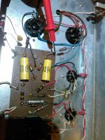
But there are also some 2k resistors attached right to pin 5. Would these be for bias?
Also, there should be 1meg resistors right on the input jacks - mine seem to read all over the place - most consistent reading I can get from them is ~10ohms - likely that these are just bad I assume?
Lastly - any light that can be shed on how this cardboard-ish circuit board is laid out? I keep trying to trace paths and running in to these little eyelets which make it hard to see where things are going.
here are the "extra" 2k resistors on the 6v6 pin 5
Im having trouble getting consistent readings on a few of them.
The schematic shows .1uf caps connected to pin 5 on both 6v6s while the ones in the amp say .22 on them...
Also there seem to be some extra resistors coming off pin5 on both 6v6s.
The schematic shows 220k and 100k resistors around the .1uf caps (which are actually .22 on my amp) both of which I found. (though they all read about 10% high)
But there are also some 2k resistors attached right to pin 5. Would these be for bias?
Also, there should be 1meg resistors right on the input jacks - mine seem to read all over the place - most consistent reading I can get from them is ~10ohms - likely that these are just bad I assume?
Lastly - any light that can be shed on how this cardboard-ish circuit board is laid out? I keep trying to trace paths and running in to these little eyelets which make it hard to see where things are going.
here are the "extra" 2k resistors on the 6v6 pin 5
Attachments
The input jacks have a built-in switch which shorts out the 1M grid leak resistors, when nothing is plugged in.
Changing the 0.1uF coupling caps on the 6V6s to 0.22uF would not make any great difference, but a more typical mod might be to change them to 0.022uF, to reduce blocking distortion.
The 2k resistors on pin 5 are grid stoppers. They improve stability of the amp, among other things.
Changing the 0.1uF coupling caps on the 6V6s to 0.22uF would not make any great difference, but a more typical mod might be to change them to 0.022uF, to reduce blocking distortion.
The 2k resistors on pin 5 are grid stoppers. They improve stability of the amp, among other things.
By setting your meter for a continuity test (with the amp powered off and caps drained) you could check where the connections are going when they run into an eyelet. Just test all the likely looking points for continuity with the other end of the wire. Maybe create a simple diagram to show how the connections go. It should correspond with the schematic, of course.
SUPER excited - first repair was a success!
Pretty sure the main issue was the dead 220k resistor on the first preamp tube plate.
I replaced that and 3 or 4 others - as well as a couple caps. Things works and sounds good!
Im probably going to use this as a tinkering/learning amp and continue to change out old parts - also maybe mod it a bit?
Thinking about trying to install a master volume so I can push the preamp section to get it to break up - amp is super clean all the way up to near full volume.
Was also reading about the negative feedback resistor it has, and thinking of changing its value (increasing it should make the amp break up earlier?)
Maybe tweaking the tone stack just for fun!
Can anyone tell me about the second preamp tube in this amp design? It looks like the plate of the first half is directly feeding the grid of the 2nd half - is this what is called a cathode follower?
Thanks so much for the tips so far! you guys are awesome!
The Three R's - Read Rob Robinette
Glad it's alive again.
Then you need to read a bit of Rob Robinette's Amp stuff
To quote Rob
I don't think I can improve on that advice
Glad it's alive again.
I'm probably going to use this as a tinkering/learning amp and continue to change out old parts - also maybe mod it a bit?
Thinking about trying to install a master volume ...
Then you need to read a bit of Rob Robinette's Amp stuff
To quote Rob
Rob Robinette said:If you are here to learn how tube amplifiers work I recommend you start with How Tube Amps Work and How Tubes Work, then read How the 5E3 Deluxe Works to see the differences between the super simple 5F1 Champ and the slightly more complex 5E3 Deluxe. Next read 5E3 Deluxe Modifications and Voicing an Amp to learn how changing components can affect the amp's tone.
I don't think I can improve on that advice
...
Was also reading about the negative feedback resistor it has, and thinking of changing its value (increasing it should make the amp break up earlier?)
...
Can anyone tell me about the second preamp tube in this amp design? It looks like the plate of the first half is directly feeding the grid of the 2nd half - is this what is called a cathode follower?
...
The right-hand triode of the second 12ax7 (looking at the schematic) is a cathodyne phase inverter. (It has 100k load resistors on both the cathode and the plate.)
Yes, increasing the value of the 82k feedback resistor will reduce the amount of negative feedback. This would increase the overall gain of the amp, causing breakup at an earlier point on the volume control, while the maximum output power of the amp will stay the same. You can try disconnecting it altogether to see if you prefer the sound and ‘feel’ without negative feedback.
By the way, according to the schematic, there seems to be no difference between the LO and HI input circuits.
If that is the case, an interesting option might be to try an ECC832 (12DW7) in the V1 position. It has one triode high gain (like an ECC83) and the other triode low gain (like an ECC82). JJ makes them in current production.
If that is the case, an interesting option might be to try an ECC832 (12DW7) in the V1 position. It has one triode high gain (like an ECC83) and the other triode low gain (like an ECC82). JJ makes them in current production.
OH man! Rob Robinettes site is great! Been staying up too late reading around there for a couple days. Looking at doing the 3-way negative feedback switch and the master volume (pre phase inverter)
SO much good stuff there (also love Uncle Dougs youtube channel)
Didnt notice about the HI and LO being the same - would that change via swapping one of the 1Meg resistors for another value?
Not too worried about that - may just end up using one of the jack holes for a master vol pot anyway.....
Gonna have to start thinking about building an enclosure for this guy soon now! more pictures (and sounds?) to follow!
Just noticing that the pre phase master vol mod on Robs site is suggesting replacement of the grid leak resistor on the phase inverter - but my amp doesnt seem to have one! The plate of V2A is jumped directly to the gride of V2B - is it possible to stick a coupling cap and resistor between these?
Or maybe just run a post phase master vol.....
Or maybe just run a post phase master vol.....
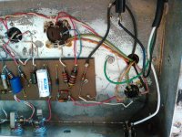
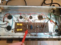
So now Im having trouble figuring out if and where the negative feedback resistor is...
The resistor/cap im pointing at in the picture dont seem to be in the schematic.... At least I was able to match up all the others - the resistor is a 1.8k and I cant tell what the cap is without pulling it out.
The resistor directly to the right (going to pin 3 of the 2nd preamp tube) is also a 1.8k.
...It seems like there is an extra resistor - or maybe one of them is the negative feedback resistor? It seems like a low value for it. Having trouble tracing where the OPT wire goes after it disappears under the board. (continuity check shows it popping up in a few places....)
Attachments
Just noticing that the pre phase master vol mod on Robs site is suggesting replacement
of the grid leak resistor on the phase inverter - but my amp doesnt seem to have one!
Sounds like you have a circuit similar to this, with direct coupling between the two stages.
http://www.angelfire.com/electronic/funwithtubes/images/Amp-Williamson-1.gif
- Status
- This old topic is closed. If you want to reopen this topic, contact a moderator using the "Report Post" button.
- Home
- Live Sound
- Instruments and Amps
- Semi-Noob trying to make sense of my first project