Hello. Thought I'd share a new (old) project of mine. Running 100W of twin 6550C's into home made 10" quad box caused my ears to bleed. My first valve (tube for the yanks) amp used 12AX7 and 12AX7 as phase splitter into EL84. sounded pretty decent, based off the AX84 project design (circuit, not design).
Anyhow, about 5W I can overdrive with my Peavey Vandenberg gat without going deaf.
I intend three inputs, may be Fender, Marshall etc. Separate 12AX7's, so I can fiddle.
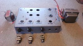
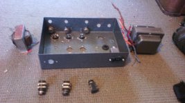
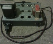
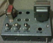
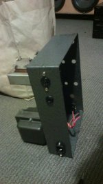
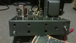
Below are some photos of an old chassis I acquired (for a song) that I have stripped and I intend on building from the ground up a baby twin to the holden Wasp (1968) that sits next to the grunter! I might use a 10" or 12" speaker, hopefully a Celestion or something if bank manager turns blind eye!
My background is in electronics and generally blowing things (projects) up.
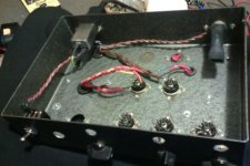
I have added mains socket and next will be mains fuse + switch. Included will be a standby switch. I will start with s/s diodes first though. Running an appropriately rated series resistor will add some "sag" (compression) same as tube diodes, right??? Will add some voltage drip for 300V B+ etc too...
I know the chassis looks like a warm turd, but I intend, from the outside world for it to look old / manky. I like the look!
Thanks. More images + blurb to follow...
Anyhow, about 5W I can overdrive with my Peavey Vandenberg gat without going deaf.
I intend three inputs, may be Fender, Marshall etc. Separate 12AX7's, so I can fiddle.
Below are some photos of an old chassis I acquired (for a song) that I have stripped and I intend on building from the ground up a baby twin to the holden Wasp (1968) that sits next to the grunter! I might use a 10" or 12" speaker, hopefully a Celestion or something if bank manager turns blind eye!
My background is in electronics and generally blowing things (projects) up.
I have added mains socket and next will be mains fuse + switch. Included will be a standby switch. I will start with s/s diodes first though. Running an appropriately rated series resistor will add some "sag" (compression) same as tube diodes, right??? Will add some voltage drip for 300V B+ etc too...
I know the chassis looks like a warm turd, but I intend, from the outside world for it to look old / manky. I like the look!
Thanks. More images + blurb to follow...
Attachments
Last edited:
Cool ") keep us updated.
keep us updated.
That´s not an ugly chassis but a roomy one .... which you´ll need to house all those preamps anyway
Not sure about your volume problems though, I always thought you could always point speakers towards the Great Outback and blast away without much concern
keep us updated.That´s not an ugly chassis but a roomy one
.... which you´ll need to house all those preamps anyway Not sure about your volume problems though, I always thought you could always point speakers towards the Great Outback and blast away without much concern
An externally hosted image should be here but it was not working when we last tested it.
Thanks JMFahey! I see you are "down under" as well. Check the flag, I am in NZ! Sadly your link (photo) does not show up. Grumbling about not being able to link to that site, or something...
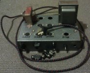
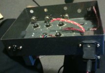
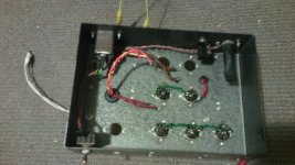
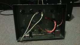
Progress. Got to find a 1A mains slow-blow fuse... See if the filament voltage is 6.3V or 12.6V. There is two large diameter windings. Might be 6.3v and something else???
Some more photos of mains wiring. Earth continuity is <0.5Ω, which is good. Will check for leakage after I find a fuse. Mains tranny should be good.
Yes, lots of space mate! I love it. My first amp build (another AX84 build) was really tiny... Was no fun to work in.
Attachments
Last edited:

"Miscounted the tiny stars, thought you were an Ozzie"
Yes me Ancestors fought for that flag! Flag is similar to the Aussie one from a distance. Just that NZ as a land mass that is slightly smaller than Aussie (tongue in cheek!). S.A. is pretty close to NZ isn't it? S.A. is closer though... Not to be confused with S.A.
I will plan on updating my wee amp project as I can. Cooking dinner at the mo... Listening to my new home grown speakers!
Last edited:
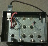
Well, ran 6.3VDC into the 12AX7's. It lives! I also drilled and fitted rear 6.5mm speaker socket and drilled out hole and installed rubber grommet for the speaker wiring from xformer to 6.5mm socket. That is about it really for now. I have to find some more valve sockets. I have some ceramic ones here somewhere for the dual-diode rectifier. I will wire a couple of 1N4007s in there for now.
I might go push-pull EL84's as my trannie is double-ended. I should have some more time to do some more work on it tomorrow, may be get the valve filaments glowing with the onboard tranny.
I might go push-pull EL84's as my trannie is double-ended.
I should have some more time to do some more work on it tomorrow, may be get the valve filaments glowing with the onboard tranny.Attachments
I've heard Aus referred to as the West Island....may as well be with the number of Kiwis over here.S.A. is pretty close to NZ isn't it? S.A. is closer though...

Dan.
I must respect people who kept the mighty Ford Falcon alive, decades after it disappeared from USA.
Which we also did, of course
As a side note, I learnt "Australian" before I learnt proper "English" , so much so that I had to "unlearn" it before my Cambridge trained English teachers would fully accept me, they were appalled at my accent.
Which we also did, of course
As a side note, I learnt "Australian" before I learnt proper "English" , so much so that I had to "unlearn" it before my Cambridge trained English teachers would fully accept me, they were appalled at my accent.
Well I have revisited my amp project and decided to use a different valve line-up. As the mains trannie o/p's both 6.3V AND 5V filament voltages (with assumed 5K impedance), I decided to use a 5Y3 rect. valve. This will use the 5V tap to glow fire. I then decided to use p/p 6V6 valves at the output instead of the EL84's. The chassis is rustic , grey and cool.
I just like the look of the old octals. I am planning a 15W project here based on the Fender 5E3. It will be a bit more powerful than I need right now (I do have a twin 6550C with 800V on the plates, 100W o/p amp !!!, so I am no pussy!), but I intend on repairing my other amp (EL84 single ended o/p based off of the AX84 project) for practice. So the 5E3 uses a 12AY7 as the preamp valve, instead of the 12AX7. No worries. I have thus far got the mains trannie fired up and all mains wiring + neon + fuse working. I also have all filaments glowing. I had to file out larger holes and fit the octal sockets for the 2 x 6V6 and the 5Y3, which was a PITA. Photos to follow!
Here she is with tubes glowing...


I read that wiring up two forward biased 1N4007, 1kV, 1A PIV diodes in series with each of the rect's anodes is a good idea (longevity of life of the 5Y3's cathodes).
But I may just as well wire up said diodes instead of the 5Y3 for a bit (50V ?) more grunt and 6V6 goodness, although I have not too much experience with 6V6 fire-tubes performance (Tweed Deluxe anyone?).
o/p of mains trannie is 325-0-325 VAC.
I can add a 20W or so resistor in series with HT+ to simulate 'compression' (B+ V-sag) as required.
I need to run some AC into the o/p trannie (20 volts or so) and measure AC o/p, as I need to figure out the o/p taps. Then I can wire up the 6.5mm o/p socket.
I will run an 8 ohm, 20W 'dummy / idiot' resistor on the o/p as a dummy-load once the amp is complete, just in case the speaker is unplugged (just thinking out loud).
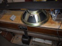
I also have a 12 inch, 8 ohm, 40W instrument speaker out of a Yamaha (Japanese) electronic organ. should work ok, but may be not as good as a Jansen or a Celestion.
I just like the look of the old octals. I am planning a 15W project here based on the Fender 5E3. It will be a bit more powerful than I need right now (I do have a twin 6550C with 800V on the plates, 100W o/p amp !!!, so I am no pussy!), but I intend on repairing my other amp (EL84 single ended o/p based off of the AX84 project) for practice. So the 5E3 uses a 12AY7 as the preamp valve, instead of the 12AX7. No worries. I have thus far got the mains trannie fired up and all mains wiring + neon + fuse working. I also have all filaments glowing. I had to file out larger holes and fit the octal sockets for the 2 x 6V6 and the 5Y3, which was a PITA. Photos to follow!
Here she is with tubes glowing...
I read that wiring up two forward biased 1N4007, 1kV, 1A PIV diodes in series with each of the rect's anodes is a good idea (longevity of life of the 5Y3's cathodes).
But I may just as well wire up said diodes instead of the 5Y3 for a bit (50V ?) more grunt and 6V6 goodness, although I have not too much experience with 6V6 fire-tubes performance (Tweed Deluxe anyone?).
o/p of mains trannie is 325-0-325 VAC.
I can add a 20W or so resistor in series with HT+ to simulate 'compression' (B+ V-sag) as required.
I need to run some AC into the o/p trannie (20 volts or so) and measure AC o/p, as I need to figure out the o/p taps. Then I can wire up the 6.5mm o/p socket.
I will run an 8 ohm, 20W 'dummy / idiot' resistor on the o/p as a dummy-load once the amp is complete, just in case the speaker is unplugged (just thinking out loud).
I also have a 12 inch, 8 ohm, 40W instrument speaker out of a Yamaha (Japanese) electronic organ. should work ok, but may be not as good as a Jansen or a Celestion.
Attachments
Last edited:
...which is waaay better than one way rectification with that single EY88 diode....I decided to use a 5Y3 rect. valve.
Best regards!
... There is two large diameter windings. Might be 6.3v and something else??? ….
Maybe a 5V winding for a tube rectifier, such as GZ34?
"...which is waaay better than one way rectification with that single EY88 diode.
Best regards!"
True. Would introduce a nasty 100Hz hum, I bet! (We use 50Hz mains here).
"Maybe a 5V winding for a tube rectifier, such as GZ34?"
Ah the 5AR4. I did not know that the GZ34 uses 5V fils! I wonder if they are an octal socket, as that is what I have fitted... Looks like it is! I do have one in a box somewhere too.
Cheers.
- Status
- This old topic is closed. If you want to reopen this topic, contact a moderator using the "Report Post" button.
- Home
- Live Sound
- Instruments and Amps
- New Guitar Practice Amp Taking shape...