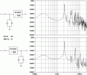
Here’s an example: A circuit consisting of a hi-pass filter @ 1kHz and a pair of clipping diodes. The input is a complex wave consisting of two sinusoidal waves. Frequency response of both circuits is identical, so is clipping threshold and clipping characteristics (pattern of harmonic distortion) with sinusoidal wave input. Only difference of the circuits is whether the hi-pass filter is located before or after the clipping diodes.
If the signal passes the circuit unclipped and undistorted you will not hear a difference in output signals of these two circuits. If clipped, they sound very different. This is explained by introduction of intermodulation distortion and by the fact that the post clipping hi-pass filter leaves higher magnitude for lower frequencies to contribute to intermodulation distortion.
Basically intermodulation distortion will add sum and difference frequencies of all fundamental frequencies – and their harmonics.
Look at FFT plots: In both cases fundamental and few of the following lower order harmonics of 246 Hz component are attenuated due to filter while fundamental of 2093 (and upper harmonics) Hz remains unattenuated. Everything else is by-product of both harmonic and intermodulation distortion. The striking difference is in the amount of those other harmonics created by the intermodulation process. You can see that the other plot with post clipping filter is rather “convoluted” due to that. The circuit that attenuates lower frequencies before clipping has strikingly lesser amounts of overall distortion.
Note: This was plotted with a “complex” wave that consisted only of two frequencies. When you pluck a single note a guitar signal probably introduces about 11 harmonic frequencies in addition to the fundamental so you can guess that in practice the IMD is much, much worse than it is already in this little example. The overall concept, however, should be pretty clear.
Attachments
getting oscillations in distortion circuit
I was wondering if anyone had some insight or idea into why this circuit is oscillating. Anyhow this is a distortion circuit similar to a boss Ds-1 circuit, but a different input buffer, and instead of an op amp with gain 22, I used a follower into a simple class a transistor amplifier gain 22. Then there is a tone circuit.
Anyhow, if you turn the guitar volume to 1 out of 10 or lower, you get oscillation with the drive pot on the circuit turned all the way up at the very top of the pot rotation, in other words when there is not series resistance between stages. So I measured the resistance required to prevent oscillations and then multiplied by 3. That ended up being 2.2k so I inserted a series resistor 2.2k.
Also similarly when the drive volume all the way down, guitar at 1, same thing, oscillation. So I varied a resistor until the oscillation disappeared and multiplied by 3. That ended up being 270 ohms, so that is between the pot and ground.
Circuit seems to work fine like that. If anyone has insight into what is happening. I guess these resistances must be interrupting a positive feedback between the stages coming through somehow.
Should I introduce feedback somewhere in the circuit to stabilize it somehow? Do I need to "decouple" the stages in some way. Or should I just leave these resistors there and consider it "fixed"?
Attachments
Common emitter stages can oscillate, but they usually aren't as touchy as common source (FET) or common cathode (valve) stages. Still, why not add a "base stopper" and see if that does the trick?...you get oscillation with the drive pot on the circuit turned all the way up at the very top of the pot rotation, in other words when there is not series resistance between stages.
Also, this sort of thing (oscillations when a pot is turned either towards ground, or towards max gain) is often caused by layout, grounding, or power supply decoupling issues.
Are all those transistors running off the same B+ rail? If yes, that could be the problem; you might try inserting the same sort of RC power supply decoupling filter that you see in every valve guitar amp power supply schematic.
In similar vein, do you have any filter caps across the power supply, from +9V to ground? None are shown in the schematic. You almost certainly need both a big fat electrolytic cap (say 100 uF), and a parallel small ceramic or film cap (say 0.1 uF). The small cap in parallel is to take care of supply decoupling at high frequencies, where electrolytic caps don't work well (too much effective series resistance and inductance).
One more thought: do you, by any chance, have this assembled on a breadboard? The dozens of closely-spaced metal strips inside a breadboard can cause nightmarish problems with stray capacitance and unwanted coupling everywhere. Building a high-gain, multi-stage amplifier on a breadboard is often a frustrating exercise in futility.
That is one way to look at it, you may have positive feedback through the +9V supply rail due to excessive impedance at high frequencies (lack of bypass caps), or positive feedback through a bad ground layout, or positive feedback because the output signal is being coupled back to an earlier stage by stray capacitance.I guess these resistances must be interrupting a positive feedback between the stages coming through somehow.
Guitar cables and pickups can act as RF antennae, feeding RF and noise into the input of anything they are plugged into. That's why most guitar preamps have some sort of series input resistor right before the first active device. I don't see anything like that in your circuit, either.
If the problem is being caused by poor supply decoupling or layout, that is the thing to address first - tackle the cause of the problem, rather than try and cover it over with a Bandaid, you know.Should I introduce feedback somewhere in the circuit to stabilize it somehow?
Good luck!
-Gnobuddy
Thanks you teemuk for the explanation of the intermodulation distortion. I think once I finish my distortion unit I will roll off different amounts of bass and listen by ear to get the most pleasing result. I also considered rolling off the bass to 200hz thereabouts or wherever the circuit sounds pleasing, and then put a variable rolloff up to say 1k therabouts as a bass control and worry about the midrange and treble controls later on in the signal path.
Thank you very much Gnobuddy for looking at this circuit. My power supply is a Truetone 1 SPOT power supply that people use for stomp box type pedals.
Yes I am using a breadboard, and wasn't too particularly careful in the layout just sort of hooked everything up and everything is hooked up to the same positive rail. I have been studying basic circuits but still haven't put a lot of complicated circuits from simulation to breadboard.
I will try the "base stopper", series input resistor, and add the 2 bypass capacitors to see how that works.
I am not familiar with the "RC power supply decoupling filter that you see in every valve guitar amp power supply schematic." Are those the 100u electrolytic and .1 ceramic cap you were talking about?
That's a nice power supply, I use one myself. However, by the time the power gets down several feet of wire to the stomp pedal, the stray inductance of the wire itself would cause many audio circuits (or stomp pedals) to oscillate wildly. The cure is simple, there will be filter caps across the power supply rails inside the stomp-box, and there should be in any audio circuit you build, too.My power supply is a Truetone 1 SPOT
They are nice for quick prototyping of simple audio circuits, but in my experience, when many amplification stages and/or high gain are involved, breadboards become useless.Yes I am using a breadboard
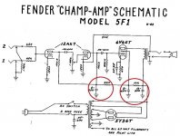
That's a big no-no, see attached schematic of an old Fender Champ. Leonidas was an accountant, so he would never spend a penny on an unnecessary part - even so, that champ has three filter caps, with two resistors separating them (inside the red circles).everything is hooked up to the same positive rail.
What this does, basically, is create separate, clean, power for the output valve (6V6) anode, for the screen grid of that same 6V6, and for the preamp valve (12AX7). Those RC filters prevent noise and signals from one of those stages leaking back to other stages, causing oscillation and instability.
Simulation is a wonderful tool, but the simulated world is often nicer and more polite than the real world. In the world of LTSpice, there is no such thing as a bad layout, there are no stray capacitances, there are no unwanted power supply rail impedance at high frequencies, et cetera.I have been studying basic circuits but still haven't put a lot of complicated circuits from simulation to breadboard.
")
See attached image. One rule of thumb is to never run more than two valve gain stages off the same B+ rail. With opamps, the rule is to have decoupling capacitors right next to the power supply pins for every single opamp. With transistors? They are usually less sensitive than opamps and valves (because of less gain and lower impedances respectively). But the "no more than two devices on the same B+" rule of thumb might be a good starting point, at least.I am not familiar with the "RC power supply decoupling filter that you see in every valve guitar amp power supply schematic."
Kinda - Leonidas' amp just uses a 16uF electrolytic cap as the first filter/decoupling cap, then two more 8uF electrolytics.Are those the 100u electrolytic and .1 ceramic cap you were talking about?
I don't know why he didn't use smaller ceramic or film caps in parallel, perhaps to save a few pennies, or because he found out he could get away with it?
The small caps are intended to take over at high frequencies, where the electrolytic caps stop behaving like capacitors, and start to behave like inductors. Those little small-signal transistors you're using are very fast, they work quite well at RF frequencies, so we have to make sure the power supply rails are well behaved even at frequencies up to several MHz. Otherwise your "audio" circuit can turn into an RF oscillator instead!
-Gnobuddy
Attachments
Made a few changes and no more oscillation
Thanks Gnobuddy for the review of the circuit. Very helpful and educational.
I made 2 changes that did the trick, first I added a 1k supply line resistor and 10uf ceramic capacitor to separate the first stage which has the highest gain from the rest of the circuit which has much less gain comparatively. This dropped the voltage from 9.5v measured to 8.5v measured across the series resistor. This fixed the problem except when the drive control was at 100%. The "base stopper" seemed to stop that problem. (I was guessing a "base stopper" was a resistor right before the base, I hadn't heard that term before.) I then added bypass caps positive/negative rails (not shown) which might have made it a little less noisy but not much change. Its still assembled on the experimenters solderless breadboard, so if it works there hopefully will work fine if I were to solder it. Oh and in the schematic I put a tonestack, volume and follower at the end of the circuit and ran it into a 22k input impedance power amp to 12" open back cabinet for listening. Thank you very much for the help. The other thing I was wondering about was about decoupling stages in the multistage design. It seems to me like you'd lose a little voltage everytime you add a supply line decoupling resistor (and cap) between stages.
Seems like this could get tricky. Maybe you'd put the supply right at the stage with the highest current, and the stages with less current (higher resistance seen by power supply) would get decoupled. Or you could place the power supply entry into the circuit such that the least amount of decoupling resistors are needed. Or you could decouple several stages and when designing each stage, plan for different supply voltages for each stage. Most usually the power supply would enter at the last stage then as it would need the highest voltage to allow maximum voltage swing. Anyhow, thanks for the help. Still interested to know if there is a rule of thumb when deciding what capacitor to use with the resistor in the supply line. I guess it should act like a filter for oscillations trying to get from stage to stage along the power supply line.
Attachments
Last edited:
Excellent, isn't it fun when theory and practice actually agree?I made 2 changes that did the trick
I was just being silly, I have never seen the term "base stopper" in any of the hundreds of books on solid-state electronics that I've read over the decades. Since "toobs" are popular here on diyAudio, I borrowed a term usually used in thermionic emission land.(I was guessing a "base stopper" was a resistor right before the base, I hadn't heard that term before.)
That's true. I haven't seen it really become a major issue though, unless you have a very limited power supply voltage (like the 9V you're using), and also need to use a lot of discrete gain stages for some reason.It seems to me like you'd lose a little voltage everytime you add a supply line decoupling resistor (and cap) between stages.
Lots of discrete gain stages is pretty much a thing of the distant past - if you need that much gain, you can usually get it much more easily from one or two opamps.
I have seen circuits that run a lot of opamps off the same (usually regulated) +/- 15V rails. There will still be a decoupling capacitor mounted very close to every opamp power pin, but no dropping resistors in the supply rails.
In the heyday of record players and cassette decks, you did need lots of audio gain, because cassette playback heads and some record pickups, put out audio signals that were very weak, often less than a millivolt.
Then again, if the signal levels are really small, you didn't really need enormous power supply voltages to cope with them!
These days, there aren't many applications where you need a lot of audio gain. The audio signals coming out of your PC, MP3 player, DVD player, et cetera, are already at least at line level, and may even be several volts.
I think microphones are probably one of the few contemporary audio signal sources that are quite weak, and so need a lot of amplification. You don't see that many DIY mic preamps these days, probably because they need good design, layout, shielding, and well filtered power supplies.
Electric guitars put out signals up to a volt or two peak-to-peak when vigorously strumming big fat chords, but that drops to a few tens of millivolts if you gently pick single strings.
If you have to get those single-note runs up to, say, ten volts peak to peak at the guitar speaker (1.5 watts into an 8 ohm speaker, which can be very loud), you need a voltage gain of 1000x, or 60 dB.
And that still doesn't leave you any extra gain for overdrive - if you want some of that, you may need another 20 dB of gain, so now we're talking about 10,000x, or 80 dB.
So you can easily see why guitar amps - especially "old-school" discrete valve designs - are going to need lots of gain stages.
I would also suggest that +9V is really a marginal supply voltage for anything guitar-related. The problem comes from the "up to a volt or two" output of the guitar. A circuit powered by a 9V power supply is unlikely to put out much more than 6V peak to peak of output without clipping. So that means that, if you want to be able to play clean strummed chords (2V signals from the guitar pickup), you are limited to a maximum voltage gain of only about 2x (that's +6 dB)!
Most solid-state guitar amps these days will use at least 30 V DC (+/- 15V rails) and opamps in the input stages. Valve guitar amps have a real advantage here, because with 300 volts or so of power supply to play with, the input stage is not in much danger of being inadvertently overdriven.
By the way, some high-output humbuckers will, indeed, overdrive the traditional 12AX7 input stage. Not because the anode signal with its huge 300-volt B+ runs out of room, but rather because the grid-cathode bias is only about 1.5 volts DC, so the guitar pickup can actually take the valve into grid current territory (less than -0.9 v bias or so), and cause clipping right at the input grid itself!
Filter, exactly. So you can do better than a rule of thumb. You can calculate the amount by which you want your 60 Hz or 120 Hz power supply ripple voltage to be attenuated, and then choose the filter frequency accordingly.Still interested to know if there is a rule of thumb when deciding what capacitor to use with the resistor in the supply line. I guess it should act like a filter for oscillations trying to get from stage to stage along the power supply line.
For example: suppose we want 120 Hz supply ripple to be attenuated to one-tenth of original strength (-20 dB). We know a first-order filter has attenuation proportional to frequency, so we'll want a filter corner frequency (-3 dB frequency) of about 12 Hz. That will ensure that the filter will have about 20 dB of attenuation by the time we get to 120 Hz.
That corner frequency for a first-order RC filter is given by the usual first-order RC filter equation: f3dB = 1/(2*pi*R*C). f is in Hz, R in ohms, C in Farads.
You can rearrange the formula to find, say, C (capacitance) with a little middle-school algebra: C = 1/(2*pi*R*f3db).
If we put in, say, R = 1k and f3dB = 12 Hz, we find that C = 13.27 uF. The exact value is not critical at all, and a bigger capacitor would give us better ripple filtering. So we could use, say, a 22 uF capacitor, and get a bit better than 20 dB of ripple attenuation.
Or, since 22uF is quite a small capacitor by today's standards, we could try using a smaller R (to reduce DC voltage drop) and see if we can still make our desired 12 Hz corner frequency. As an example, if we used R = 100 ohms (ten times less than 1k), we would need ten times more capacitance, or about 132 uF; we might as well use 220 uF.
Or we might decide to stick with a 1k resistance, but try for 40 dB of ripple attenuation. -40 dB is one-hundredth, so we now need a corner frequency a hundred times lower than 120 Hz; that's 1.2 Hz. You can probably see immediately that 132 uF (or, practically speaking, 220 uF) will get us there.
So you can choose to juggle the amount of attenuation you want, the value of R (which also decides DC voltage drop), and the value of C, until you find a balance you are happy with.
As usual, "the proof of the pudding is in the eating". If your circuit is stable, and quiet enough, then you have enough power supply decoupling and filtering!
-Gnobuddy
General questions about preamp design and decoupling, biasing etc.
Thanks Gnobuddy and everyone else for all the information. Sorry for the delay. I wanted to study up more before I reposted.I was thinking I would try and use discrete building for awhile for learning until I feel like I've gotten pretty comfortable and then move on to op amp circuits. I agree it would certainly be better to have more voltage than 9 volts. Its really tough to squeeze everything into 9 volts especially with a really peakey guitar input signal.
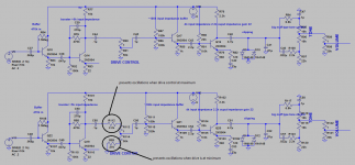
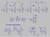
Here are some general questions about guitar preamp circuit designs. They probably belong after the long paragraph tirade below them but in case I have written to much here are some specific questions I have been pondering. (see attached image for questions 2-5)
1) ground lift - should I put on on the preamp, if so, at input, output or both. Can I just put a ground lift on all the time instead of a switch and just leave a fixed ground lift?
2) supply line decoupler - when using more than one decoupler, should they be in series along the supply rail or just above each stage in parrallel (see attached image)
3) When using resistor dividers to make bias voltages for stages, can you
string them all in series or should they be in parallel, or does it not matter. (see attached image)
4) I noticed a diode in opposite direction of biasing resistor on some schematics, is this some type of protection to transistor? I saw this when using darlington configuration. Maybe it has something to do with that. (see attached image)
5) shunt feedback vs. class A. I've seen both used. I have made circuits with both and am generally able to design the biases and gains, etc, (although input impedance of shunt feedback a little tricky) When I need a certain stage, I am not sure when to pick which type. Is one more stable or otherwise adventageous? (see attached image)
6) When the guitar is not plugged into the input on the amp, should the input be grounded with a switched jack for lower noise? Also I saw on an amplifier schematic I was studying a high and low gain input to presumable deal with very hot guitar pickups. Is there a very simple circuit for doing this. The one I looked at appears to just lower the input impedance at the amplifier, which I think could actually potentially change the signal substantially.
About some of the other comments:
As far as gain goes, I like the sound of the Boss DS-1 pedal, as I may have mentioned there is a transistor booster stage gain 56 (according to one webpage) followed by an op amp gain 22. So I thought why not just add a transistor stage with gain of 22, I ought to be able to get a gain of 22 out of a transistor stage. So that's how this circuit started. Now gain 56 x gain 22 = 1232, which basically is way too high for many tastes, so people even mod the pedal to lower the gain. At any rate I don't think I would have gone for gain that high if I hadn't been making a transistorized clone of the pedal.
I read as much as I could find on decoupling stuff, but not a lot of in depth stuff is available online, but I wasn't sure exactly how to approach decoupling multiple stages. In the fender champ schematic, I saw that referred to in one source as "supply line decoupling" where you basically decouple in series, the effective voltage available for each stage falling every time you decouple. However, I also saw some circuits in which people just automatically put a decoupler on the collector of the amp stage. See figures 3 and 4 at BIPOLAR TRANSISTOR COOKBOOK — PART 4 - Nuts & Volts Magazine - For The Electronics Hobbyist
Gnobuddy mentioned guitar clipping at the input (paraphrasing). One of the things I did since last post is study a schematic of an amp I have a "Peavey Bandit 112" "Transtube" series. It was a good study for me and helped me understand the circuitry a little better. It has no op-amps in the preamp section at all and is entirely transistor. It has a DC bias at 1.5v on some of the stages.
(From Peavey "In devising the TransTube Circuitry, our engineers studied every aspect of how a tube amp works. We learned that recreating tube tone isn't merely a question of gain structure. It's about the entire component chain and how each one interacts with the others.")
I would reproduce some of the schematic for conversation but I don't think I'm allowed to. Anyhow, it has multiple gain stages, the first 2 at 30v, then a decoupler, then the next 2. Actually the decoupler is in sort of in a power supply type area one labelled 28 v and the other 30v. There are Darlington stages, a feedback R2 (loop)/R1(series resistor before input) darlington configuration and a very hard driven clamp that resembles a Baker's clamp driven with massive gain. Interesting at least to me, they didn't worry too much about signal loss, correct impedance matching during some filtering etc for maximal signal transfer.
It has some stages biased at 1.5v, and if I strum very hard (les paul 498t bridge) I can get a crackle.
So they put a "high gain" and "low gain" input, to knock the signal down a little.
This brings me to another point. It seems to me like a soft clipper to take some peaks away would go a long way toward helping a guitar signal. I think you can make a fairly soft clipper somewhere in the signal path to help out if you take a very low resistance output stage, feed it into a fairly low series resistor, then a 2 or 4 diodes. see link (Soft Clipping).
To me this seems much more important for the clean signal, because a lot of the disorted signals at least that I have been working with are going to be clipped down anyhow.
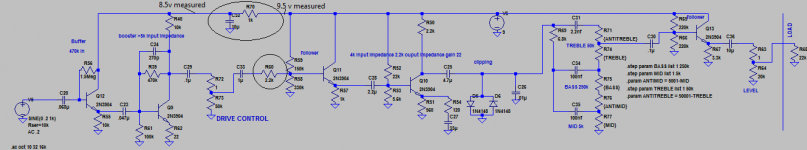
I used some of the concepts I've been learning in the attached circuit I made today. Basically I made a clean/distorted channel preamp, but left the distortion out, this way, I can insert whatever disortion circuit with gain control the preamp to test out different ideas.
It has a gain of about 3.0. 0.5 peak amplitude x3 = 1.5v amplitude ~1vrms. (The emitter voltage is set at .935 and collector is at 5.1v. The emitter waveform starts to hit the collector waveform when the signal is .85v or a bit lower.) So any signal above .85, in practice probably .8 (1.6v peak to peak) will clip. I may just employ a high and low gain input type schematic if I want to keep a 9 v supply.
Thanks Gnobuddy and everyone else for all the information. Sorry for the delay. I wanted to study up more before I reposted.I was thinking I would try and use discrete building for awhile for learning until I feel like I've gotten pretty comfortable and then move on to op amp circuits. I agree it would certainly be better to have more voltage than 9 volts. Its really tough to squeeze everything into 9 volts especially with a really peakey guitar input signal.
Here are some general questions about guitar preamp circuit designs. They probably belong after the long paragraph tirade below them but in case I have written to much here are some specific questions I have been pondering. (see attached image for questions 2-5)
1) ground lift - should I put on on the preamp, if so, at input, output or both. Can I just put a ground lift on all the time instead of a switch and just leave a fixed ground lift?
2) supply line decoupler - when using more than one decoupler, should they be in series along the supply rail or just above each stage in parrallel (see attached image)
3) When using resistor dividers to make bias voltages for stages, can you
string them all in series or should they be in parallel, or does it not matter. (see attached image)
4) I noticed a diode in opposite direction of biasing resistor on some schematics, is this some type of protection to transistor? I saw this when using darlington configuration. Maybe it has something to do with that. (see attached image)
5) shunt feedback vs. class A. I've seen both used. I have made circuits with both and am generally able to design the biases and gains, etc, (although input impedance of shunt feedback a little tricky) When I need a certain stage, I am not sure when to pick which type. Is one more stable or otherwise adventageous? (see attached image)
6) When the guitar is not plugged into the input on the amp, should the input be grounded with a switched jack for lower noise? Also I saw on an amplifier schematic I was studying a high and low gain input to presumable deal with very hot guitar pickups. Is there a very simple circuit for doing this. The one I looked at appears to just lower the input impedance at the amplifier, which I think could actually potentially change the signal substantially.
About some of the other comments:
As far as gain goes, I like the sound of the Boss DS-1 pedal, as I may have mentioned there is a transistor booster stage gain 56 (according to one webpage) followed by an op amp gain 22. So I thought why not just add a transistor stage with gain of 22, I ought to be able to get a gain of 22 out of a transistor stage. So that's how this circuit started. Now gain 56 x gain 22 = 1232, which basically is way too high for many tastes, so people even mod the pedal to lower the gain. At any rate I don't think I would have gone for gain that high if I hadn't been making a transistorized clone of the pedal.
I read as much as I could find on decoupling stuff, but not a lot of in depth stuff is available online, but I wasn't sure exactly how to approach decoupling multiple stages. In the fender champ schematic, I saw that referred to in one source as "supply line decoupling" where you basically decouple in series, the effective voltage available for each stage falling every time you decouple. However, I also saw some circuits in which people just automatically put a decoupler on the collector of the amp stage. See figures 3 and 4 at BIPOLAR TRANSISTOR COOKBOOK — PART 4 - Nuts & Volts Magazine - For The Electronics Hobbyist
Gnobuddy mentioned guitar clipping at the input (paraphrasing). One of the things I did since last post is study a schematic of an amp I have a "Peavey Bandit 112" "Transtube" series. It was a good study for me and helped me understand the circuitry a little better. It has no op-amps in the preamp section at all and is entirely transistor. It has a DC bias at 1.5v on some of the stages.
(From Peavey "In devising the TransTube Circuitry, our engineers studied every aspect of how a tube amp works. We learned that recreating tube tone isn't merely a question of gain structure. It's about the entire component chain and how each one interacts with the others.")
I would reproduce some of the schematic for conversation but I don't think I'm allowed to. Anyhow, it has multiple gain stages, the first 2 at 30v, then a decoupler, then the next 2. Actually the decoupler is in sort of in a power supply type area one labelled 28 v and the other 30v. There are Darlington stages, a feedback R2 (loop)/R1(series resistor before input) darlington configuration and a very hard driven clamp that resembles a Baker's clamp driven with massive gain. Interesting at least to me, they didn't worry too much about signal loss, correct impedance matching during some filtering etc for maximal signal transfer.
It has some stages biased at 1.5v, and if I strum very hard (les paul 498t bridge) I can get a crackle.
So they put a "high gain" and "low gain" input, to knock the signal down a little.
This brings me to another point. It seems to me like a soft clipper to take some peaks away would go a long way toward helping a guitar signal. I think you can make a fairly soft clipper somewhere in the signal path to help out if you take a very low resistance output stage, feed it into a fairly low series resistor, then a 2 or 4 diodes. see link (Soft Clipping).
To me this seems much more important for the clean signal, because a lot of the disorted signals at least that I have been working with are going to be clipped down anyhow.
I used some of the concepts I've been learning in the attached circuit I made today. Basically I made a clean/distorted channel preamp, but left the distortion out, this way, I can insert whatever disortion circuit with gain control the preamp to test out different ideas.
It has a gain of about 3.0. 0.5 peak amplitude x3 = 1.5v amplitude ~1vrms. (The emitter voltage is set at .935 and collector is at 5.1v. The emitter waveform starts to hit the collector waveform when the signal is .85v or a bit lower.) So any signal above .85, in practice probably .8 (1.6v peak to peak) will clip. I may just employ a high and low gain input type schematic if I want to keep a 9 v supply.
Attachments
That's certainly the original historical progression - people had to figure out how to work with these newfangled transistor thingies, which were very different from vacuum tubes, and develop new circuit topologies that played to their strengths....discrete building for awhile for learning...then move on to op amp circuits.
But, with all the hard design work now decades behind us, I'm not convinced that the best path for a newcomer to electronics is to retrace history. From the users point of view, op amp circuits are simpler. All the hard stuff is hidden inside the chip, but the whole chip is really easy to use - sort of like a super-transistor, with vast amounts of clean gain, simple biasing requirements, and extremely precise behaviour controlled by a resistor or two.
Is there value in learning the details of how things work inside the opamp? Yes, certainly, but it's not necessary in order to use opamps in simple circuits. As a crude analogy, most people who drive cars today don't have a clue what an oxygen sensor is, or what role it plays in keeping the engine running properly.
I hate "black boxes" myself, and would prefer to understand every little detail, but the world has gotten complex to the point where I have been forced to the realization that this isn't possible any more. Much of the workings of the PC I'm typing this at is a mystery to me...
Yeah, it's unfortunate that 9 volts became the standard for guitar effects pedals. I'm guessing this was probably driven by the limitations of the early germanium transistors, not to mention the cost of batteries.I agree it would certainly be better to have more voltage than 9 volts. Its really tough to squeeze everything into 9 volts especially with a really peaky guitar input signal.
If we're talking about mains-powered circuitry, the combination of the phrases "ground lift" and "guitar amplifier" make me very nervous. When you play guitar, your fingers are in intimate contact with the guitar strings, which in turn are grounded through the guitar cable to the guitar amp.1) ground lift - should I put on on the preamp, if so, at input, output or both. Can I just put a ground lift on all the time instead of a switch and just leave a fixed ground lift?
So if the amp chassis is not solidly grounded, the guitarist is in peril - any voltage on the chassis will flow through the guitarist to ground. And he/she might not even be able to let go, because electric shock causes the muscles to contract, and it is quite likely the fretting hand will clamp onto the guitar strings with a death-grip. The word "death" might well become literal, here.
So, my suggestion is no ground lift, ever, in any kind of guitar amp. We want that amp chassis solidly grounded any time the amp is plugged in.
Series implies lots more filtering - each successive stage in the chain removes more ripple, so the DC is very clean when it gets to the most sensitive (input) stages of the amp. But series resistors involve more DC voltage drop along the way.2) supply line decoupler - when using more than one decoupler, should they be in series along the supply rail or just above each stage in parallel (see attached image)
In the era of vintage valve amps, when electrolytic caps were expensive and limited in capacity, and there was plenty of B+ voltage, series filtering was an obvious choice.
I'm not sure I understand the scenario you have in mind. But if it works, doesn't make nasty noises, and is stable, it's a good design!3) When using resistor dividers to make bias voltages for stages, can you string them all in series or should they be in parallel, or does it not matter. (see attached image)
Looks to me like the diode is designed to keep the transistor base from going more than 0.6V more positive than the positive rail. This might protect the collector-base junction from going into forward bias and potentially being destroyed.4) I noticed a diode in opposite direction of biasing resistor on some schematics, is this some type of protection to transistor?
These are completely unrelated concepts. If only one transistor is amplifying both positive and negative halves of the audio signal, it has to be class A. Oversimplifying slightly, every preamp circuit you've shown is class A, and you have no choice in the matter.5) shunt feedback vs. class A.
Note that a class A circuit may have no feedback, it might have series feedback, or it might have shunt feedback. The same goes for class B, class AB, and class C. Once again, there is no connection at all between "class A", and "shunt feedback" or "series feedback". They are entirely independent concepts.
I think you're asking about the two biasing schemes in diagrams E and F, right?Is one more stable or otherwise advantageous?
If I understood you correctly, the answer is to be found in the family traits of transistors. One trait is that transistors have very wide spreads in current gain - the same part number may have a current gain of 250, or 900, or anywhere in between, and you won't know unless you measure it.
Another trait is that the voltage drop from base to emitter, with the transistor operating normally, is almost guaranteed to be somewhere between 0.6 volts and 0.7 volts. It varies slightly from one transistor to another, and also varies slightly with collector current, but will still usually be in that small range between 0.6 V and 0.7 V or so. Unfortunately, though, for any given transistor, changing that base voltage by a very tiny amount causes huge changes in collector current - in fact, an 18 mV change will double the collector current!
So, if you're an electronics engineer circa 1950, trying to figure out how to bias these new transistor contraptions, what do you do? You can't bias by setting the base current - the wide spread in current gain will cause huge variations in collector current. And you can't do it by setting the base-emitter voltage, either - there's no way you can set it accurately enough to get the collector current you want.
Some clever person figured out a third option. You set the base voltage (not base-emitter voltage, just base voltage with respect to ground). You let the emitter settle where it wants, within roughly 0.6V - 0.7V of that base voltage. And then you connect a resistor from emitter to ground, and Ohm's Law will set the emitter current for you. Done!
What I have just described is your circuit "E". For the NPN transistors you show, the base voltage will ideally be sufficiently positive so that normal variations in VBE (0.6 - 0.7V) cause very small changes in the emitter current. I would suggest the base be at least at +2.7 volts with respect to ground. The emitter will then be at about +2 volts. The emitter resistor will set the emitter current.
This works very well when you have sufficiently high supply voltage. But note that we've lost 2 volts DC at the emitter, so with your low 9V supply, there are now only 7 volts remaining for the collector. The transistor should have at least 1V DC across it at all times to operate properly, so that leaves you only 6V peak-to-peak signal at the collector. That's only about 2 volts RMS. Anything bigger, and you hit clipping!
Also, circuit "E" uses a lot of components. Four resistors and three capacitors per transistor (input cap, emitter bypass cap, coupling cap from collector to next stage.)
Your circuit "F" is a later evolution of "E". If the current through the transistor increases for any reason (including higher than expected current gain, or lower than expected emitter-base voltage), there is some feedback that attempts to correct the error.
I'm not very fond of "F", myself. The feedback lowers the (already low) input impedance. Circuit "E", if properly designed, already works well. And finally, the future of transistor amplifier design went in an entirely different direction - both "E" and "F" became obsolete.
The new direction was DC coupling first two, then gradually more, transistors, until eventually a fully DC-coupled transistor amplifier emerged from the process. The next step was to put that on an integrated circuit, and the modern solid-state opamp was born.
My opinion, yes. Why would you not want to do this, right?6) When the guitar is not plugged into the input on the amp, should the input be grounded with a switched jack for lower noise?
Leo Fender was (a) a cheapskate, and (b)not an engineer. He found a way to use two or three resistors and a switching jack to provide some slight difference in input sensitivity (and input impedance). Generations of subsequent "designers" slavishly copied Fender....high and low gain input...appears to just lower the input impedance at the amplifier..
It is not a great design, partly for the reason you mentioned, and also because thermal noise from those resistors at the input turns into hiss at the loudspeaker.
In the early days of transistor guitar amps, there was lots of discrete circuitry. Some used BJTs, a few of the better (later) ones used JFETS. Eventually opamps took over.Peavey....transtube...no op-amps in the preamp section at all and is entirely transistor.
To my ears, none of them sound anywhere near as good as a properly designed valve guitar amp. A lot of them sound outright horrid to me.
Yeah, sure, I bet "You can't tell it's not butter!""We learned that recreating tube tone isn't merely a question of gain structure. It's about the entire component chain and how each one interacts with the others."
In my opinion, at least 99% of solid-state electric guitar amplifiers fall into the category of the dozens of "fake butter" products you see in the supermarket. They all claim to taste just like the real thing. And almost all of them actually taste utterly horrid!
A tip - many, many HP inkjet printers use(d) a power supply that puts out +16V and +32 volts DC. These power supplies can often be found for a buck or two at thrift stores. Add a little filtering (series R, C to ground), and they make nice DC supplies for preamp experiments.one labelled 28 v and the other 30v.
Interesting, right? I'm pretty sure a nasty crackle is not most musicians idea of good guitar tone!It has some stages biased at 1.5v, and if I strum very hard (les paul 498t bridge) I can get a crackle.
To me, every diode clipper circuit sounds utterly horrid, nasty, awful. Like the early fuzz-boxes....soft clipper...fairly low series resistor, then a 2 or 4 diodes. see link (Soft Clipping).
If you add some filtering to strip away some of the harsh high harmonics, and then a delay pedal to soften it a bit more, and then some reverberation (electronic or from the room), you can get some guitar tones many will like.
But clipping diodes on their own? Yikes. Comparing a few silicon diodes to the sound of a good valve stage? Double yikes.
I have great respect for Rod Elliott's circuit design chops as showcased all over his website. But whenever he discusses "musical distortion" in guitar amps, I start to wonder if we are from the same planet. He seems to be suggesting that raw diode clipping sounds good, and 10% valve (tube) distortion is too much. To put it very politely, my ears cannot make any sense out of either claim.


-Gnobuddy
simple compressor
Thank you so much Gnobuddy and all others for your help. I would not have been able to get my preamp running without your help which was insightful and invaluable.
Gnobuddy, PRR, JMFahey, rayma, etc and anyone who has helped me on this project, please PM me your address and I will send you a completed/assembled preamp I ended up with. I ordered some pcbs and got 6, so I'd love to send a completed preamp if you'd like one, and feel free to critique the sound if you'd like, would appreciated any feedback.
I agree op amps are "simpler". But I just like figuring things out.
When I was talking about ground lifting I meant putting a very small resistor in series to the ground of the input jack of the guitar preamp. But no worries its not so important.
As far as there being a low and high gain input jacks on a guitar amp, I've seen circuits that change the input impedance, like Gnobuddy was referring to. In my preamp I have a single 1Meg biasing resistor going to base of an emitter follower to set the bias voltage and input impedance. So I think I'm just going to put a resistor in parallel to this with a switch to simulate going from a "low gain" to "high gain" input jack. I haven't tried this but it seems a lot easier than adding two switching jacks to my preamp.
I completely understand what you're talking about with the diode clipper circuits sounding bad. I have built at least 100 bad sounding clipping circuits while experimenting with this stuff.
But I have made one that I think sounds good.
It took my lots of trial and error/experimenting to get it sounding nice, but I am very pleased with it.
I found that the soft clipping diode pair/feeding back ( from collector to base in a transistor circuit http://www.generalguitargadgets.com/wp-content/uploads/ric_onetrans.gif) was about the best thing to start with. So I tried driving it harder and that caused nasty waveforms, which I thought was a shame because I thought that could be a promising approach. So what I did was run the common collector amp dc coupled to an emitter follower, and ran the diode feedback from the emitter follower circuit back to the base instead. In other words instead of feeding back the collector to base, I fed the collector to a follower and then fed followers emitter back to base. This AC decouples the circuit which in itself is nice, but allows you to drive the circuit much harder, which is the real advantage. I planned on recording with a condenser mic what I was hearing and apply some filtering in a digital audio workstation to get it sounding nicer. Then I would build some filters around those results. But instead opted to do this manually with notch filters. I used an inductor a series resistor to vary Q and tried capacitors by hand until I got the filtering I wanted. Then to avoid the inductor I built a gyrator which worked well but ultimately built a similar bridge t filter for simplicity that worked well enough. After this filter, I hard clipped the peaks with grounded diodes and ran into another tonestack filter.
In summary there is an "overdrive" leading into soft clipping circuit, into a bridge t, then a hard clip of peaks, then more tone stack filtering. I am extremely pleased with the sound. To me it sounds better than any solid state amp I have owned, but of course I built it to sound what I thought was ideal, and that can be different for different people.
If anyone wants the schematic posted I would be happy to post.
Originally I thought maybe the boss ds-1 type circuit might work out ok but this blows that away.
Regarding the boss Ds-1, I did find a nice and easy way to replace the op amp with fewer parts (2 transistors) and sounds just fine. I'm including it in the post for completeness in case anyone happens on this thread interested in building an all transistor Boss Ds-1 distortion. Fewer parts simpler, etc. The whole circuit is not shown just the op amp replacement.
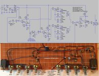
One other circuit I came up with is a relatively simple compressor. I'm also very happy with how this works. This is for the clean channel of the preamp. It has 2 controls, threshold and compression, and uses a 5mm flat red led contacting a photoresistor (I used '5549' photoresistor). I put them next to each other and used a lighter and heat shrink tubing, no glue. The heat shrink tubing molded easily around everything was really simple to do. (Mash the heat sink tubing around the legs while its hot also, may need gloves or a moist paper towel) It has an indicator LED so you can see when the signal is going above threshold. The LED comes on simultaneously with the vactrol. Very rudimentary but seems to work fine. In the circuit it looks like I'm rolling off a lot of bass on the LED driver and I am. I had to roll off a lot more than I thought I would have to. The LED still comes on with all strings including the low E. Rolling of the bass stuff really helped with artifact and distortion I believe because the wavelength/period is too long for low notes. The circuit shown has 4 transistors, but I will only need to add 3 transistors to the clean channel of my preamp to put the compressor in, so its an easy add on to what I've already built.
I am working on another simple compressor that uses a few transistors and no vactrol, but I'm not sure how it will end up sounding. Its going to kick on and off differently and a lot "harder" compression, so I'm not sure what result I will get. I'm going to use an envelope follower to a transistor switch that pushes a resistor to ground and changes gain of the signal. It'll be interesting to see what it sounds like.
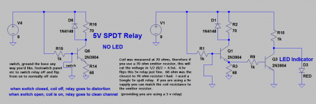
Also if anyone reading this thread is interested, I've shown the relay circuit I'm using for channel switching. I tried several different circuits this one worked the best. I made the circuit so that any way you choose to ground the base of the transistor relay driver, that will shut off the relay. So I have a switch on the panel of the preamp and a footswitch which goes to ground. The coil has current going through it while the clean channel is on, and no current in coil while on distorted channel. The high gain/distorted channel was picking this up the coil, so I found it better to leave on during clean channel state. I also added an LED indicator, which added just the slightest amount of noise while the distortion was on. When I say noise I'm talking about all gains set to maximum, it was not as noisy as a typical distortion pedal or the peavey amp I have. Definitely was usable. I didn't scrap it because of noise, I really scrapped the LED indicator on my preamp because i didn't care to have it.
Thank you so much Gnobuddy and all others for your help. I would not have been able to get my preamp running without your help which was insightful and invaluable.
Gnobuddy, PRR, JMFahey, rayma, etc and anyone who has helped me on this project, please PM me your address and I will send you a completed/assembled preamp I ended up with. I ordered some pcbs and got 6, so I'd love to send a completed preamp if you'd like one, and feel free to critique the sound if you'd like, would appreciated any feedback.
I agree op amps are "simpler". But I just like figuring things out.
When I was talking about ground lifting I meant putting a very small resistor in series to the ground of the input jack of the guitar preamp. But no worries its not so important.
As far as there being a low and high gain input jacks on a guitar amp, I've seen circuits that change the input impedance, like Gnobuddy was referring to. In my preamp I have a single 1Meg biasing resistor going to base of an emitter follower to set the bias voltage and input impedance. So I think I'm just going to put a resistor in parallel to this with a switch to simulate going from a "low gain" to "high gain" input jack. I haven't tried this but it seems a lot easier than adding two switching jacks to my preamp.
I completely understand what you're talking about with the diode clipper circuits sounding bad. I have built at least 100 bad sounding clipping circuits while experimenting with this stuff.
But I have made one that I think sounds good.
It took my lots of trial and error/experimenting to get it sounding nice, but I am very pleased with it.
I found that the soft clipping diode pair/feeding back ( from collector to base in a transistor circuit http://www.generalguitargadgets.com/wp-content/uploads/ric_onetrans.gif) was about the best thing to start with. So I tried driving it harder and that caused nasty waveforms, which I thought was a shame because I thought that could be a promising approach. So what I did was run the common collector amp dc coupled to an emitter follower, and ran the diode feedback from the emitter follower circuit back to the base instead. In other words instead of feeding back the collector to base, I fed the collector to a follower and then fed followers emitter back to base. This AC decouples the circuit which in itself is nice, but allows you to drive the circuit much harder, which is the real advantage. I planned on recording with a condenser mic what I was hearing and apply some filtering in a digital audio workstation to get it sounding nicer. Then I would build some filters around those results. But instead opted to do this manually with notch filters. I used an inductor a series resistor to vary Q and tried capacitors by hand until I got the filtering I wanted. Then to avoid the inductor I built a gyrator which worked well but ultimately built a similar bridge t filter for simplicity that worked well enough. After this filter, I hard clipped the peaks with grounded diodes and ran into another tonestack filter.
In summary there is an "overdrive" leading into soft clipping circuit, into a bridge t, then a hard clip of peaks, then more tone stack filtering. I am extremely pleased with the sound. To me it sounds better than any solid state amp I have owned, but of course I built it to sound what I thought was ideal, and that can be different for different people.
If anyone wants the schematic posted I would be happy to post.
Originally I thought maybe the boss ds-1 type circuit might work out ok but this blows that away.
Regarding the boss Ds-1, I did find a nice and easy way to replace the op amp with fewer parts (2 transistors) and sounds just fine. I'm including it in the post for completeness in case anyone happens on this thread interested in building an all transistor Boss Ds-1 distortion. Fewer parts simpler, etc. The whole circuit is not shown just the op amp replacement.
One other circuit I came up with is a relatively simple compressor. I'm also very happy with how this works. This is for the clean channel of the preamp. It has 2 controls, threshold and compression, and uses a 5mm flat red led contacting a photoresistor (I used '5549' photoresistor). I put them next to each other and used a lighter and heat shrink tubing, no glue. The heat shrink tubing molded easily around everything was really simple to do. (Mash the heat sink tubing around the legs while its hot also, may need gloves or a moist paper towel) It has an indicator LED so you can see when the signal is going above threshold. The LED comes on simultaneously with the vactrol. Very rudimentary but seems to work fine. In the circuit it looks like I'm rolling off a lot of bass on the LED driver and I am. I had to roll off a lot more than I thought I would have to. The LED still comes on with all strings including the low E. Rolling of the bass stuff really helped with artifact and distortion I believe because the wavelength/period is too long for low notes. The circuit shown has 4 transistors, but I will only need to add 3 transistors to the clean channel of my preamp to put the compressor in, so its an easy add on to what I've already built.
I am working on another simple compressor that uses a few transistors and no vactrol, but I'm not sure how it will end up sounding. Its going to kick on and off differently and a lot "harder" compression, so I'm not sure what result I will get. I'm going to use an envelope follower to a transistor switch that pushes a resistor to ground and changes gain of the signal. It'll be interesting to see what it sounds like.
Also if anyone reading this thread is interested, I've shown the relay circuit I'm using for channel switching. I tried several different circuits this one worked the best. I made the circuit so that any way you choose to ground the base of the transistor relay driver, that will shut off the relay. So I have a switch on the panel of the preamp and a footswitch which goes to ground. The coil has current going through it while the clean channel is on, and no current in coil while on distorted channel. The high gain/distorted channel was picking this up the coil, so I found it better to leave on during clean channel state. I also added an LED indicator, which added just the slightest amount of noise while the distortion was on. When I say noise I'm talking about all gains set to maximum, it was not as noisy as a typical distortion pedal or the peavey amp I have. Definitely was usable. I didn't scrap it because of noise, I really scrapped the LED indicator on my preamp because i didn't care to have it.
Attachments
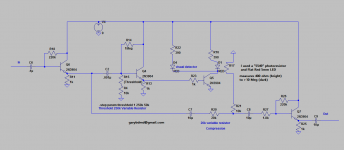
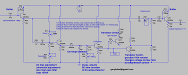
Here's my try at a simple transistor guitar compressor with no vactrol
Here's my try at a simple compressor. Basically I got the idea that I would change the resistance ratio of a voltage divider to change the gain using a transistor as a switch, forcing a resistor to ground when the transistor comes on. Basically the threshold is changed by changing the biasing resistors of an emitter follower. This leads into an envelope follower (diode detector), with variable time constant or attack/decay. When the envelope detector gets above .7v about, the transistor switches on and pushes the resistor to ground lowering the gain. The compression amount can be adjusted by varying the top resistor in the voltage divider. I played my guitar through it and it seems to work. To set up the threshold, you set all pots all the way up and then adjust the resistor (labelled floor) down until the indicator led comes on fully around .7 volts where the transistors switch on/off (labelled node). Then turn the threshold down so the led is peaking. You'll hear the gain change pretty obvious. Then lower the decay to acceptable level by lowering the RC resistor in the envelope detector. Then you can lower the compression amount. I'm not actually sure if this qualifies as a compressor in the sense that once threshold is reached the whole signal drops, but you can for highly dynamic guitar peaks I think it seemed to work. I would like to try it out on a mix and see what it sounds like.
Thanks for looking and please any suggestions appreciated. It would be nice if anyone knows any simple improvements on an envelope detector, this detector is about as rudimentary as it gets.
Attachments
Over the years there have been a few circuits in electronic magazines for ADSR (attack,decay,sustain,release) envelope shapers. Usually using some IC or other.
There are a few compressors around usually using a mosfet to control output signal. The mosfet gate is controlled from the audio signal rectified.
There are a few compressors around usually using a mosfet to control output signal. The mosfet gate is controlled from the audio signal rectified.
Please advise on most common or standard output level for preamp
I have just about finished this guitar preamp I have been working on and I need to figure what the output level should be?
The preamp is designed to go into a power amp which then goes into a speaker cabinet. I am wondering what level do most power amps expect?
Should I set the maximum level to be:
a) .707 vrms or 1 v amplitude?
b) 1 vrms or 1.414 v amplitude?
c) 1.414 rms or 2v amplitude?
I was thinking of looking at the peak values on an oscilloscope of the clean channel and setting that to be 1.414v maximum, and then setting the distorted channel to be a little under that maybe about 80% of the clean channel.
I more or less want to be able to drive a typical power amplifier. In my days they were crown, bgw, etc.
The effects out on the preamp can be used for lower level stuff around 300-400mv for pedals etc, but the final stage will drive a power amp.
Any help appreciated!
There is a standard of sorts for pro-audio equipment like those Crown power amps: nominal line level sensitivity is +4 dBu, which is the same as 1.23 volts RMS, or roughly 3.5 volts peak to peak.I more or less want to be able to drive a typical power amplifier. In my days they were crown, bgw, etc.
It's debatable how much pro-audio equipment actually sticks to the standard, but at least it's a starting point.
With your preamp running on 9 V DC, output voltage is automatically limited to a maximum of maybe 8 volts peak to peak (allowing for a bit of lost voltage due to saturation of the output BJT).
This leaves very little safety margin (headroom) between full power from the power amp, and clipping of the preamp - only about 6 dB (i.e. the change from 3.5 V to 8 V).
This is one reason why most solid-state preamps run on +/- 15 volt rails, you get a bit more headroom that way.
Valve guitar amps are a different kettle of fish entirely. I suppose in the days of rack-mount separate power and pre amps for guitar there was some sort of standard input level for power amps. But the typical Fender or Marshall or whatever has no such thing as a standard power amp sensitivity. It seems to have been more or less randomly determined by the B+ supply voltage and the voltage gain of the various stages in the power amp (phase splitter, output stage, etc), plus the effect of any global negative feedback in the power amp.
As you probably know, there is another standard line level for consumer audio devices, this time, -10 dBV, which is 316 mV RMS, or just under 1 volt peak-to-peak.
Guitar effects seem to have yet another "standard" line level, sometimes called "instrument level", which is usually around -20 dBV, or 100 mV RMS, or 280 mV peak to peak.
There is quite a wide gulf between the nominal -20 dBV output of most guitar FX pedals, and the +4 dBu line-level input sensitivity of the typical audio mixer. This has been a cause of headaches for me, as some time ago I started to run my guitars, electric bass, and vocal microphone all through a little Mackie mixer, and the different levels and input impedance requirements forced the use of various kludges.
-Gnobuddy
Pro power amps usually have a gain of 20 (26dB). They are not following the +4dBu convention, though the result is in the same ballpark.
You can't really get too "exact" in your calculations. You have gain/volume knobs, use them to taste. Gain of 100 ahead of the Crown will get soft guitar up to pretty loud.
You can't really get too "exact" in your calculations. You have gain/volume knobs, use them to taste. Gain of 100 ahead of the Crown will get soft guitar up to pretty loud.
input sensitivity
Thanks PRR for your answer.
I went through musicians friend website, and just looked at the specs for the most popular power amplifiers. Not all of them had good information, on the amps that listed specs on the website, here is what I found:
Gemini XGA-2000 Power Amplifier Input Sensitivity 0.77v
Crown XLS1002 2-Channel 350W Power Amp Sensitivity: 1.4Vrms
QSC GX3 Stereo Power Amplifier Input Sensitivity: 1.2 Vrms
Behringer EP4000 EUROPOWER Power Amp Input sensitivity: 1.15V (+3.4dBu) VRMS at 8Î
Crown XLS1502 2-Channel 525W Power Amp Sensitivity: 1.4Vrms
QSC GX5 Stereo Power Amplifier Input Sensitivity: 1.2 Vrms
Electro-Voice Q44 II Power Amplifier Input Sensitivity (rated power @ 8 ohms, 1kHz): +2.2 dBu(1vrms)
Where input sensitivity is defined as the minimum voltage required to achieve maximum power output of the amplifier.
But I am guessing it is better to have higher output available at the preamp and turn down the volume on the power amp.
With guitar, it seems there are huge variations in expected signal level between one guitar and another, and one guitar player and another.But I am guessing it is better to have higher output available at the preamp
On a different diyAudio thread, we have one person who can reproducibly get 10 volt (yes, ten volt) peaks out of his electric guitar. A number of other people have seen up to 1.5 V peaks from their guitars. Guitar FX pedals seem to be designed to accept about 100 mV peaks. And Fender amp datasheets seem to specify 20 mV at the guitar input for full output.
So should we be expecting ten-thousand millivolts, or twenty millivolts?
Evidently, we have to be at least somewhat prepared to have to deal with the possibility of either, or anything in between.
I think this is why there is such a wide range of gain control available in good mixers, in addition to the volume control on the power amp(s).
I think a 9V power supply is really too low for guitar devices, though it has become the standard for FX pedals by an accident of history.
Fortunately, we rarely mind if there is some compression and squashing on a guitar signal, so the inability of the 9V supply to deliver enough output signal isn't as much of a problem for guitar electronics, as it would be for, say, a microphone preamp for vocals.
-Gnobuddy
- Status
- This old topic is closed. If you want to reopen this topic, contact a moderator using the "Report Post" button.
- Home
- Live Sound
- Instruments and Amps
- signal chain in guitar preamp, boost before eq or eq before boost