Hi Again Folks!
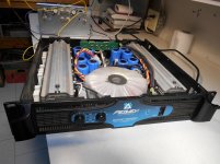
Well, I'm back at 'Step 1'; Admitting I'm powerless over the still suffering Amplifier! I have just purchased a Peavey GPS 3500, aware that channel A was not functioning. This is obviously not a particularly 'Hi Fi' amp, but at a rated 775 Watt/chan into 8 ohms, I thought it might be a worth-while project.
I have had great success on a number of projects, with the help of expert members of the Diyaudio forums, so I thought I would introduce the project before ripping into it, 'bull in china shop' style.
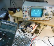
I tested the functioning channel, and saw that it could develop almost 745 watts across my 8 ohm furnace element. The torroid transformer seems to have separate windings for each channel, channel A was discovered (and remains) disconnected.
Well, I'm back at 'Step 1'; Admitting I'm powerless over the still suffering Amplifier! I have just purchased a Peavey GPS 3500, aware that channel A was not functioning. This is obviously not a particularly 'Hi Fi' amp, but at a rated 775 Watt/chan into 8 ohms, I thought it might be a worth-while project.
I have had great success on a number of projects, with the help of expert members of the Diyaudio forums, so I thought I would introduce the project before ripping into it, 'bull in china shop' style.
I tested the functioning channel, and saw that it could develop almost 745 watts across my 8 ohm furnace element. The torroid transformer seems to have separate windings for each channel, channel A was discovered (and remains) disconnected.
Attachments
")
The 'soft start' resistors show obvious signs of over-heating, so I thought it pointless to plug in channel A and attempt powering up the unit, even through a variac. Just wondering if anyone has any suggestions before I disassemble this amp. I have no experience with trouble-shooting class H (if that's what this 2 tier power rail amp is) but I thought I would start with checking output devices. I am hoping that 'in circuit' measurements, comparing Left and Right channels will give me some clues.
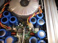
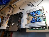
BTW, I have tamed a Crest CA-18 (1000 watt/chan, 8 ohms) for subwoofer use in my home theatre system, (a 39 page thread titled; "Toroidal Transformer Noise"). The Peavey seems to be a cheaper cousin to the Crest, with a one-peace PCB design, rather than modular sections, BUT, the torroid is dead quiet, at least with one channel connected, and the fans apparently stay off, rather than 'slow' until heatsinks reach 45 degrees C., making this amp a contender for (large) home subs.
BTW, I have tamed a Crest CA-18 (1000 watt/chan, 8 ohms) for subwoofer use in my home theatre system, (a 39 page thread titled; "Toroidal Transformer Noise"). The Peavey seems to be a cheaper cousin to the Crest, with a one-peace PCB design, rather than modular sections, BUT, the torroid is dead quiet, at least with one channel connected, and the fans apparently stay off, rather than 'slow' until heatsinks reach 45 degrees C., making this amp a contender for (large) home subs.
Attachments
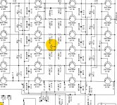
These style amps look confusing. Think of it as a standard complimentary output stage and forget about the extra row of transistors, all they do is turn on when required to keep a good overhead voltage.
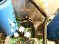
Looking at the NTC's, I'd say a dead short on an output transistor of the dead side is to blame.
Check with your Fluke, yes I have had one for many years and it has helped me repair countless items. Still in daily use.
Looking at the NTC's, I'd say a dead short on an output transistor of the dead side is to blame.
Check with your Fluke, yes I have had one for many years and it has helped me repair countless items. Still in daily use.
Thanks Jon, and all;
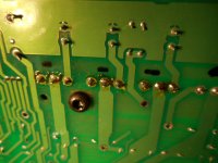
Good to know I have some 'back-up', from the start! First dumb question; What is an NTC? I assume you may be referring to the 2 damaged disc-like objects, pictured above. The schematic indicates these as simply resistors, and the parts list says they are 1 ohm 30 amp thermistors. BTW, If these thermistors are open or defective, would the amp still power on ( is the slow-start function timed, or do the power supply voltages have to reach a particular threshold?)
Also; a red LED called "DDT", (Peavey's protection system) is illuminated for the dead channel, I have not thoroughly studied the schematic, but I am guessing that it's power source is separate from the amp rails.
Thanks, I will begin disassembly, asap, Regards, Peter
NTC is negative temperature coefficient resistor.
They start off high resistance, to keep from dimming the lights in the room, then heat up & go low resistance as the rail capacitors fill up and stop drawing so much current. Newark sells GE, digikey sells some other brands with more variety. CL-21 is close for home use, 1.3 ohm cold, but in a PA venue you'd have to investigate more than 8 amps steady state current.
Also check for leaky filter cap on the dead side. Lacking an ESR meter, I like to charge them up to 2 v with ohms scale then see how fast voltage drops on 2 v scale. More than a decade of millivolts drop per scan, XXX. Compare to good caps depending on the size.
I had a 1300 w peavey that kept blowing outputs due to a dodgy solder joint on the feedback pin of the driver op amp. Kept whanging to plus rail when it heated up. Various techs didn't find it in 14 years. amp was so destroyed, outputs, emmiter resistors, VI limiter resistors, drivers predrivers, op amps, DDT stuff, 50v ceramic caps, coupla resistors, were all blown. 124 parts. A few traces were melted on the driver board. I used a room element heater for current limit on that one, the 100 W light bulb wouldn't allow enough current to let the +-15 v circuit for the op amp to function.
I put 5 amp fuses in the base lines of that one to limit the damage the next time an OT goes short. Also 2.2 v zener clamps to blow the fuses if anything gets out of spec, +-1 v on base line.
I found OT's with .450 v or below Vbe were stressed, would short out next time rail voltage got on them. The two that were .550 v or above I used as drivers. Probably not fast enough Ft for hifi, but this is PA level watts, bar customers aren't expecting hifi anyway.
Last edited:
Wow! Thanks Indianajo and Jon, for all the info! Sounds overwhelming, but I'm hopeful that it's nothing that complicated. The amp looks clean with no signs of over-heating anywhere but the thermistors! I appreciate your history with these amps.
I will get the main PCB out of the case as soon as I can steal some time. Seems like it will be a bit 'flimsy' with those large heatsinks on each side, and the narrow PCB in the middle. All info with Peavey or Crest class H amps would be helpful, I am trying to get familiar with these monsters!
Thanks, Peter
Hi Folks;
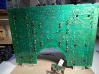
This project is moving at a snail's pace! Work is becoming a real interference in life. I have only just disassembled the Peavey. The narrowed PCB seems to be a flimsy link between the heavy ends with the heat sinks, but I think this will be the least of my problems!
This project is moving at a snail's pace! Work is becoming a real interference in life. I have only just disassembled the Peavey. The narrowed PCB seems to be a flimsy link between the heavy ends with the heat sinks, but I think this will be the least of my problems!
Attachments
Peavey does things to make the amps easily bridgeable. So you connect the two sides together without damage, as long as inputs are identical.
My PV-1.3k had "flying speaker ground" . Looks like this might have flying power supply rail. Like the rail was connected to the speaker. I'd need to see more of the schematic to tell.
My PV-1.3k had "flying speaker ground" . Looks like this might have flying power supply rail. Like the rail was connected to the speaker. I'd need to see more of the schematic to tell.
If you want the amp to work properly at high wattage, all the output transistors need to be from the same production run. Same part number helps, but there are revisions that happen that change characteristics. After you buy those, you need to match them and discard some. I use the Vce test at gain of 10, collector resistor 10 ohms, Vcc 12 v.I will check all the outputs with my fluke meter, asap, obviously this will be telling.
The outputs which have been replaced are Q 113, 115, 117, 119, and 121.
This is so at all temperatures, the transistors share current, none of them hog it and heat up too much.
If you don't need the wattage, leave the orphans out. Off the board.
Or buy a new set of OT's from Peavey. They will do the matching for you. I bet the fans they sell are better than the ones you can get at distributors, too.
Last edited:
Thanks also for the in-depth info regarding matching outputs. I have always heard about this, but to be honest, I've just 'hoped for the best' in the past. I am now doing this for the learning experience, as well as getting the amp working.
Would it be possible to show me a schematic of a test jig to compare outputs? Also, what kind of tolerance would you suggest?
Yet another dumb question; If all the (PNP) outputs are matched when replaced, how should they be matched to the (NPN) outputs in the B+ bank? Am I correct in assuming that matching B+ and B- banks is a distortion issue rather than current sharing?
Thanks again, I bet you're sorry you hooked into this!
I like BS ing about what I know. Sometimes I'm right.
I just take some clip leads and connect + of 12v battery charger (no electronics just transfomer rectifier filter cap) to a 10 ohm resistor then to the case of the npn. I connect a 100 ohm resistor from + charger clip to base. Emitter goes to - of battery charger. I put mine on a heat sink because I'm inexperienced. Voltmeter goes from case to emitter. Measure each at about the same time on because they self heat.
I had two .11 v, a lot of .12 and several .13 v. I put the two .11 v in the parts bin although they were "better" gain. Lucky since I only bought two extras.
Use opposite polarity of 12 v supply for the PNP ones. Turned out my pnp and npn were actually matched at .12 and .13 v.
Enzo is the world's expert on PA amp repair when he has time for us. He's retired now. hope he is traveling the world or persuing some really fun hobby.
As a jpg file the schematic once downloaded can be blown up and is readable. Will take a close look later.
Last edited:
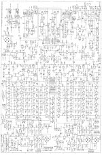
Okay, if I rotate the schematic 3 times it is right side up.
If you look at the speakon diagrams at the bottom, there is a Channel A+ out on pin 1 and Channel A- out on pin 3. Grounds are 2 & 4.
The A+ derives from J102 pin WJ10. The ground derives from J103 WJ10. I can't spot where those come from but there are +mirl A connected to one set of collectors and -mirl A connected to another set of collectors. So if they drove the two sets of transistors with opposite phases, and the emitters were grounded, then the voltage between A out + and Aout- on the speakons would be double what either would be alone to ground.
Whoa, one high power amp.
- Status
- This old topic is closed. If you want to reopen this topic, contact a moderator using the "Report Post" button.
- Home
- Live Sound
- Instruments and Amps
- Pet Peeve Peavey (GPS 3500)