Hi people... I would like to get a few comments please...
Some time ago I started building custom Guitar Amplifiers... not because I am a Muso... but rather because my (then teenage) son was.
Fast forward 15 years...
I have most recently completed a few different versions of a Solid State Guitar Amplifier modeled on the (classic) VOX AC-30. Its key attributes are:-
1. Does not use ANY Integrated Circuits (in the signal path)
2. Does not use ANY bi-polar transistors
3. Uses FET semiconductors throughout ... JFET’s (small signal) and specialist MOSFET’s (power)
4. Amp architecture / signal path / tone controls based on the (classic) VOX AC-30 amplifier
5. Uses an Output Transformer... like ALL Valve Amps... which provides significantly tonal differences to direct-coupled circuits
6. Output Damping factor of transformer is much “looser” than solid state amps
7. Lower damping factor substantially changes the dynamic characteristics of the speakers
8. Is switchable between Class A(?) (like the VOX AC-30) and Class B for more “conventional” operation. This provides some tonal differences liked by musicians (Clean / Crunch)
While I could write lots more I will perhaps wait for any specific questions and/or general interest first.
Thanks
I would love to hear more. I've daydreamed about doing a lot of the same things you did, particularly the JFET/ MOSFET/ output transformer thing. Also keeping away the large amounts of negative feedback found in most integrated opamps and power amps, for more progressive clipping behaviour.
You might also consider posting to the "Hundred Buck Amp Challenge" thread in this forum. A lot of oddball and unusual guitar amp ideas were discussed on that thread.
Elsewhere on the Instruments & Amps forum, things tend to be much more conservative, and you tend to find mostly questions about repairing mass-produced guitar amps and other electronics. Love for novel solid-state guitar amp innovations might be a bit thin on the ground.
One reason I have an interest in a decent-sounding solid-state guitar amp, is that I have a friend with a physical impairment that makes it hard for him to handle anything heavy. For some time I've been wanting to build him a decent-sounding guitar amp.
It needs to be inexpensive (because of my current financial situation, and his) and solid-state (to keep weight down). I've been thinking "JFET / MOSFET" for some time, but haven't really made a start on anything other than the housing.
-Gnobuddy
Hi Gnobuddy... sounds like we are on parallel paths here... albeit that I might be more advanced! ")
My design outlook was, as you have suggested, to get away from the "op-amp" standard design and I have, as far as possible, used the same "architecture" as the AC-30 - same number of stages; same type of stages; no negative feedback; scaled component values to match operating voltages / currents; same tone control network; etc; etc.
I have had a few Musos try it and they seem impressed. It definately has its own "sound"... rather than connecting your guitar to your hi-fi system!
As for your requirements of light weight and low cost... that might be a problem!
1) The use of an output transformer adds weight. Similarly I have used an iron-core mains transformer rather than a toroid... or even a switch-mode PSU, and,
2) The transformers add to the cost... as do the FETs - particulalry the output MOSFETs which need to be lateral (audio) devices - rather than the el-cheapo switching types.
When I get a chance I will have a look at the "Amp challenge".
Happy to continue the conversation in the interim!
Cheers
That sounds like a great project. Im sure youve seen what they have done at runoffgroove.com with modelling tube amps with fets? Though I dont think they went right through with a power amp with OT. Ive built some stompboxes that use jfets for crunch and they can sound quite convincing if setup right..
John, that website, and a few clips of surprisingly good-sounding Runoffgroove pedals I found on You Tube, was one reason I wanted to experiment with JFETs in a guitar amp.I'm sure youve seen what they have done at runoffgroove.com with modelling tube amps with fets?
I had been kicking around some theoretical reasons, too, before I ever stumbled across Runoff Groove. In a nutshell, I realized that most of the problems with typical solid-stage guitar amps come from the use of BJTs. With BJTs comes a huge excess of ugly sounding distortion, a huge excess of voltage gain, and a huge excess of negative feedback to tame the ugly distortion.
That recipe works wonderfully well for Hi-Fi, but when you apply it to a guitar amp, the cleans are sterile and "too clean". And if you try to overdrive it, it instantly goes from "too clean to be any good" to "so harsh that it's really nasty".
So the obvious starting point for a better analogue solid-state guitar amp seemed to be to go with discrete JFETs in the preamp and MOSFETS in the power amp. I was pretty sure that this would make things better, but would it make a good amp, or just a "less awful" amp?
Reading between the lines, I think GJB had/has come to some of the same conclusions independently, and I'm hoping he's about to share his answer to that question with us.
Some years ago I was quite impressed by some clips of a pedal called the "FET Dream" by C&E pedals. It was an expensive pedal, so I never seriously considered buying one, but it did serve as a demonstration that FETs at least could sound good.I've built some stompboxes that use jfets for crunch and they can sound quite convincing if setup right..
-Gnobuddy
I haven't even got off my backside and actually built anything, so yes, absolutely, without a doubt, you are far more advanced!Hi Gnobuddy... sounds like we are on parallel paths here... albeit that I might be more advanced!
Exactly!It definitely has its own "sound"... rather than connecting your guitar to your hi-fi system!
I have a solid-state amp intended for electro-acoustic guitar and vocal microphone, or as a small monitor or P.A. for keyboards, etc. It's designed to be very clean, and as "Hi-Fi" as the manufacturer could make it, given limitations on price and intended use.
I also have a (valve) Princeton Reverb reissue. An attempted (factory) copy of a vintage valve guitar amp that gained a solid reputation for good-sounding, "valvey" clean tone.
It is interesting to plug the same guitar into each amp in turn, and listen for similarities and differences. Once I dial in a similar EQ curve on both amps, guitars with very low-output pickups actually sound very similar through both amps.
But turn up the signal from the pickup, and you can hear the subtle "valvey" harmonics start to add shimmer and richness to the sound.
My friend plays rhythm guitar 90% of the time, and attempts to play kinda-sorta bass lines with his (non-bass) guitar the rest of the time. For his style of playing, he doesn't need an accurate AC-30 emulation. But the little Roland Microcube he's using now has that too-clean solid-state sound, combined with a speaker the size of my palm stuck in an open-back cabinet with a deep, deep bass response reaching all the way down to...800 Hz or so.
What I'm hoping to create for him is a better bass response, and richer clean tone (i.e., several percent of second harmonic distortion, and maybe a smattering of higher order stuff too.) The Microcube sets the bar for clean tone and bass response very, very low - so it shouldn't be too hard to do a bit better.
I would love to see as much of your design as you are willing to share, but I won't attempt to duplicate all of it for the project I have in mind. Corners will have to be cut, otherwise it won't happen at all.As for your requirements of light weight and low cost... that might be a problem!
I'll just have to be as smart as I can in terms of which corners I can cut without sounding as bad as the Microcube!
-Gnobuddy
More on FETs
Hi guys... I haven't had a chance to read your info and links at present... but will do asap.
In the interim a couple of thoughts on FETs. Firstly I noted that John's VOX box has variable resistors in the FET drains. Not a bad idea since one of the issues with FETs is that their parameters... even of the "same" type... can vary widely. Some FETs types are suffixed with Y, GR and others to try to narrow this down. Even those still vary.
However I have taken a different approach.
I tested the INDIVIDUAL Vgs and Igs of every FET I used and then used the formulas described in an article I read about how to make a FET sound like a (triode or pentode) valve. I will post a link to this when I can (re) find it.
I have not used diode limiters on the FET gates... but I am assuming this was done primarily get the over-drive characteristics?
If anyone is interested I could probably post my schematic... and talk about the output MOSFETs... and its associated transformer that I have used???
Cheers
PS... I have re-thought the $100 challenge... assuming this is in US$ it could probably be done. I work in AUS$ so that would be $140 currently!
I've found that using dual (plus and minus) supply rails helps a lot with this. The gate is tied to ground with a large value resistor, the source to a negative rail via a source resistor, the drain to the positive voltage via a drain resistor in the usual way....one of the issues with FETs is that their parameters... even of the "same" type... can vary widely.
The idea is that Vgs might vary, say, from -1V to -3V from device to device (a huge and unacceptable 300% variation). But if the source resistor is fed from, say, a (-12V) rail, the voltage across the source resistor varies between 13 and 15 volts; that's 14 volts plus or minus about 7%, an entirely acceptable variation.
This approach works quite well to set the bias current roughly where intended. But I don't know how well it does in terms of sounding like a triode.
I've read at least one article on biasing a JFET to have a similar distortion characteristic as a triode. ("Fetzer valve"). I've been a bit skeptical, because, as far as I know, an actual triode doesn't have a three-halves law once you add an anode load resistor to it! The 3/2 law only applies when the anode is held at a constant positive potential.
But if you're getting JFETs to sound enough like an AC-30 to impress guitarists, that's no minor feat!
I'm interested. I'd love for you to do those things.If anyone is interested I could probably post my schematic... and talk about the output MOSFETs... and its associated transformer that I have used???
The original challenge began some years ago (2011, I think), and eventually petered out to an unplanned end of sorts. But the thread was so full of good ideas, that some of the regulars kept it going, long after the original challenge was over and done with.PS... I have re-thought the $100 challenge... assuming this is in US$ it could probably be done. I work in AUS$ so that would be $140 currently!
The new intent of the thread was, more or less, to explore interesting guitar amps built on a fairly small budget. No more $100 constraint if you want to go over that. No more "no solid state in the signal path" constraint once imposed by the "valve purists". Just good clean guitar-amp fun.
-Gnobuddy
A dual supply is a neat idea. In my builds, I was just trying to go for the best pedal sound in a single 9V format. I tried a few different jfet models, particularly J201 and MPF102, but settled on 2N5457 as the sweet spot. But as you say, they are all wildly inconsistent, though out of my 100 pack, most have a Vgs in the range around 1.5V to 1.9V, which seems to work well with guitar signals and a simple common source circuit.
One thing I did find, is that the softness of clipping as the jfet is pushed is related to how much current is running through it, and the more that runs through at a given bias voltage, the softer the clipping. I bias them to about 5V at the drain, using typically about a 15k drain resistor to get a tone that I like. The source resistor is whatever needs to go with it for each individual jfet to bias it to a 5V drain.
I tried a 'Fetzer valve' build, but didn't find it very interesting.I tried a few of my own designs, some with tone control and some without.
This is the simplest and the last one I did, with two class A stages and a buffer. In the final version, there is a volume and a gain pot, and as gain is increased, the extra dB's are added progressively to the low mids and highs. There is a sound clip there too:
BlueJuice - an Overdrive using JFETs | GuitarNutz 2
I'd also be very interested in your AC30 build.
That makes perfect sense from the point of view of practicality. Just about every electric guitar player has other 9V pedals, and very likely, a 9V power supply for them....the best pedal sound in a single 9V format.
I do feel that the 9V legacy is sometimes a technical limitation, though. Too bad early guitar pedals didn't settle on +/- 15 V, like early opamp audio circuits did!
I'm out of luck there, I have a double handful of one of the "J" series (J211 or J212, I think), but no 2N5457s.I tried a few different jfet models, particularly J201 and MPF102, but settled on 2N5457 as the sweet spot.
Discrete JFETs are almost an extinct species now. Supplies are falling and prices are soaring. I think we can expect them to virtually disappear from the market within the next few years.
So a bigger Idss produces softer clipping? That sounds like a very useful thing to know!One thing I did find, is that the softness of clipping as the jfet is pushed is related to how much current is running through it, and the more that runs through at a given bias voltage, the softer the clipping.
Some very nice sounds there! Thanks for sharing!
-Gnobuddy
More details
Hi Gnobuddy (and others)... sorry for the delay... have been away.
Firstly a few notes on some of the comments I have seen.
1) The use of a dual (+/-15V) supply does not really make the biassing any easier. Ultimately it comes back to simply, and properly, setting Vgs whatever supply(s) are used.
2) Having said that using a larger supply is better. Biassing is easier and voltage gain is directly related to supply voltage. Having only a 9 volt supply can be limiting.
3) In my (pre)amp I used a (single) 24 volt supply - using an 7824 regulator. In the most recent design I have gone to 30 volts - but needed to use a TL783 regulator for the higher voltages.
4) I have again looked at the runoffgroove AC-30 box and it does share some, but not all, of the concepts I have used. (Obviously) it does not include the power amplifier section for one. I have also noted that this unit uses a "contouring" section... something I may investigate further.
5) I have noted the comments re the "Fetzer" design and its relevance to second and third harmonics. That debate could go on... but, in practical (listening) terms it seems to work.
6) One of the critical factors with the Fetzer is that NO source bypass capacitor should be used. Allowing the negative feedback that is produced is important. In my design I did actually use a bypass cap on the first stage... but... have used a variable pot (which I have called the "gain" control) to control it. The change of sound is noticeable. Overdrive is a bit "crunchier" (third harmonics) in max gain.
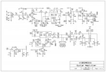
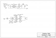
Lastly... and importantly... I have included a schematic of a slightly earlier version of my amp. Please note however:-
1) I am now using Toshiba 2SK series FET's... of which I have recently found a supply chain. (My secret!)
2) Similarly I am using 2SK1058 MOSFETs in the power stage... very important... and beware of "bootleg" versions. They do not work. Initially I used the ECX10N20's. They are OK... but the 2SK's are better... and cheaper!
3) While the component values are shown many of them are select-on-test after having measured the FET's Vgs and Igs... and applied the Fetzer calcs.
4) You will notice that the stages of the amp pretty much exactly mimic that of an AC-30... and many of the component values are "scaled" to the lower voltage used. The ratio is approx 10:1 given the higher voltage used in the valve version
5) The part of the schematic on the lower right is to do with biassing of the power stage. A "neat" little circuit (if I do say so myself!)
6) It allows for standard class AB bias... and... switching to a higher bias which approaches class A... at lower signal levels. This mimics the (higher) self-bias used in the AC-30.
7) Also... and this took a while... I have found a reasonably priced, off-the-shelf, output transformer that can be used. Initially I had some custom built... expensive!
I could probably write several pages (at least!) describing the circuit operation... but... perhaps I will leave that for the time being... and/or until I get some specific questions.
Cheers,
GJB
Hi Gnobuddy (and others)... sorry for the delay... have been away.
Firstly a few notes on some of the comments I have seen.
1) The use of a dual (+/-15V) supply does not really make the biassing any easier. Ultimately it comes back to simply, and properly, setting Vgs whatever supply(s) are used.
2) Having said that using a larger supply is better. Biassing is easier and voltage gain is directly related to supply voltage. Having only a 9 volt supply can be limiting.
3) In my (pre)amp I used a (single) 24 volt supply - using an 7824 regulator. In the most recent design I have gone to 30 volts - but needed to use a TL783 regulator for the higher voltages.
4) I have again looked at the runoffgroove AC-30 box and it does share some, but not all, of the concepts I have used. (Obviously) it does not include the power amplifier section for one. I have also noted that this unit uses a "contouring" section... something I may investigate further.
5) I have noted the comments re the "Fetzer" design and its relevance to second and third harmonics. That debate could go on... but, in practical (listening) terms it seems to work.
6) One of the critical factors with the Fetzer is that NO source bypass capacitor should be used. Allowing the negative feedback that is produced is important. In my design I did actually use a bypass cap on the first stage... but... have used a variable pot (which I have called the "gain" control) to control it. The change of sound is noticeable. Overdrive is a bit "crunchier" (third harmonics) in max gain.
Lastly... and importantly... I have included a schematic of a slightly earlier version of my amp. Please note however:-
1) I am now using Toshiba 2SK series FET's... of which I have recently found a supply chain. (My secret!)
2) Similarly I am using 2SK1058 MOSFETs in the power stage... very important... and beware of "bootleg" versions. They do not work. Initially I used the ECX10N20's. They are OK... but the 2SK's are better... and cheaper!
3) While the component values are shown many of them are select-on-test after having measured the FET's Vgs and Igs... and applied the Fetzer calcs.
4) You will notice that the stages of the amp pretty much exactly mimic that of an AC-30... and many of the component values are "scaled" to the lower voltage used. The ratio is approx 10:1 given the higher voltage used in the valve version
5) The part of the schematic on the lower right is to do with biassing of the power stage. A "neat" little circuit (if I do say so myself!)
6) It allows for standard class AB bias... and... switching to a higher bias which approaches class A... at lower signal levels. This mimics the (higher) self-bias used in the AC-30.
7) Also... and this took a while... I have found a reasonably priced, off-the-shelf, output transformer that can be used. Initially I had some custom built... expensive!
I could probably write several pages (at least!) describing the circuit operation... but... perhaps I will leave that for the time being... and/or until I get some specific questions.
Cheers,
GJB
Attachments
Thanks very much for the schematics, and your explanatory comments about your design!
I've looked at the Fetzer Valve equations (here: The "triode" emulator revisited ), and I agree that using a dual supply doesn't help with your goal, which was to set up each individual JFET as a Fetzer Valve optimized for its own individual values of Vgs, Idss, and Vp.
Using a (sufficiently large) negative supply rail does, however, help when the goal is to specify the value of Id, minimizing the effect of parameter spreads in Vgs, Idss, and Vp. I explained how this works in my previous post on the subject - basically, it reduces the percentage variation in Id caused by a given percentage variation in Vgs (which in turn depends on Vp and Idss).
On the issue of the +30V rail you're using for your JFETs - I don't know if you'll like this idea or not, but I've recently found out that a lot of Hewlett Packard inkjet printers use a 32 volt DC power supply (some have both a +16V and a +32V rail).
Old HP printers were built like tanks and would last for decades, but contemporary ones die in a year or two, and the power supplies keep on working. Around here, there is a plentiful supply of these little switching power supplies to be found in thrift stores, usually for no more than a couple of bucks, because nobody wants a 32V DC power supply.
I've used the 0V/16V/32V ones to run op-amp projects (none of the rails are grounded, so just treat the 0V as (-16V), the 16V as (0V), and the 32V as (+16V). There is some switching noise on the rails, but its very easy to filter out with a small RC filter in each supply rail.
So, if you want, small, light, efficient, regulated, 32V DC power supplies are now easy to find. No need to build your own, unless you prefer to.
-Gnobuddy
I am designing guitar amps from scratch for my personal use for a long time and so will point out some aspects that I found important.
FETs are nice for their low noise figure specially as input stage for high impedance magnetic pickups.
All in all I do not give much about "triode distortion" and "even harmonics" . This aspect is mostly over-estimated by guitar players. The different sound of overdrive stompboxes mostly results from different filtering, not from nonlinearity imho.
So there is only one JFET in the signal chain, and that is inside my axe. A source follower to buffer the signal independent of cable and vol setting.
The amps are designed for simplicity, low noise, battery powered and low weight. And for a good sound as well
There is nothing bad with opamps or bjts, as long you do not drive them into the limits. I use a mix of op-amps and discrete stage - whatever suits better.
Diode distortion might work fine, but care should be taken for a smooth transition from clean to distorted. This is why I prefer a double-ended differential pair as distortion element.
Besides this I found it useful to add some pre-emphasis / de-emphasis network to prevent bass notes blocking the upper end of a chord.
A clean HiFi-amp sounds ugly when overdriven, there is no doubt about this. Limiters often do a nice job, thus a BJT or class-D power stage is not necessaryly a show stopper.
Between my pre-amp and the TPA3118 powerstage I inserted a soft-limiting circuit that keeps output level just below clipping. Works fine for me.
Last, and perhaps most important - the speaker. This vastly is a matter of taste, there is no other way than checking it out.
For the practice amp, I use a 6.5 inch Jensen MOD15, on stage a 12" lightweight neodym celestion.
My current stage amp is powererd by a 24V= notebook adapter and delivers about 20W through TPA3118 into the 12" celestion. With its styrofoam case total weight is below 5kG.
Last edited:
I may not be typical, but I am a guitarist, and I find the vast majority of overdrive / distortion / fuzz pedals sound quite utterly horrible. Unbearable, in fact.The different sound of overdrive stompboxes mostly results from different filtering, not from nonlinearity imho.
The logarithmic distortion produced using semiconductor clipping diodes seems to be to blame. This type of distortion produces large amounts of all harmonics, and the resulting sound is very harsh and unpleasant to my ears.
You can filter out some of the harshness, but it still sounds unpleasant, till it gets to the point where it is so heavily filtered that it is unpleasant because it is muffled.
IMO one of the keys to making distortion pedals sound not-horrible is to follow them with a delay pedal. It's absolutely incredible how a bit of following delay can transform an unbearably harsh sound into a silky musical-sounding scream. I think this discovery goes back to David Gilmour in his early Pink Floyd days.
On the even vs. odd harmonic issue, what I've found is that I much prefer small amounts of mostly even harmonic distortion for "clean tones" - no audible distortion at all, just a richer and "tubier" sound.
On the other hand, for fairly heavily overdriven sounds, I prefer fairly symmetrical clipping, which generates mostly odd harmonics. I think this is because there are already so many harmonics present, that adding both even and odd harmonics to the mix only makes an even more unpleasant mess; there is no easy way to eliminate the odd harmonics, but we can at least eliminate the even harmonics with a symmetrical or push-pull design.
Just my experience - don't pay more than 2c for it, certainly.
-Gnobuddy
I end to think that a layered mix of different types of distortion yields the most pleasing and complex tones.
Now there's one important factor about the way tube preamp stages behave when overdriven; that they clip asymmetrically. In a typical triode stage the anode will rise all the way and hard clip at B+ voltage on the upswing. However, it will go into s soft limiting on the downswing and never get all the way down to 0V, With a 100k load resistor, it will limit somewhere around 50V, with rounded edges on the flattened downward swings, in contrast to the square-edged clipping of the upswing.
The cutoff on the upswing yields a harsher or somewhat fizzy distortion, limiting on the lower excursions gives a thicker, warm crunchy distortion. A triode common-cathode stage biased with the anode at half B+, will first hit soft limiting as it beginning to be overdriven, before clipping at B+. The end result sounds really good! I wonder how effectively Runoffgroove's Fetzer stage emulates that. I'm not criticizing here, just wondering.
Regarding diode clipping, I've been a huge skeptic myself for many years. However I've found from my own experience, that it depends. Different types of diodes yield different qualities of distortion, probing b related to their switching speed, whether signal diodes, rectifiers, LEDs or infrared LEDs. Some Marshall designs use IR LEDs, which sound harsh to my ears.
Just for fun, I modded a Boss DS1 pedal which had a really fizzy "wasp in a jam jar" tone, from a pair of silicon signal diodes. I removed one of them and connected it in series with the other. Then I put a cheap yellow LED in the now empty spot, and placed a 0.01uF cap across the diodes to clean up any residual harshness. It turned into a wonderful overdrive/distortion pedal, with a crunch tone worthy of any classic Marshall amp. I find myself using it constantly allowing the tube amp to overdrive and then adding more of its own crunch with increased guitar volume. This takes me back to my initial statement about having a layered mix of different flavors of distortion.
Sent from my LG-D801 using Tapatalk
Last edited:
I agree. I also agree with JohnDH that a distortion spectrum that changes progressively with signal level is also an important ingredient.I end to think that a layered mix of different types of distortion yields the most pleasing and complex tones.
With valves, this sort of progressive shift tends to happen when grid current starts to flow, and the operating point shifts in response. For triodes its the control grid, while for pentodes, the screen grid also plays a big role in producing dynamic, signal-driven, bias shifts.
Not that bias shifts always sound good (they can sound really bad if they cause blocking distortion). But get the time constants and amount of bias shift right, and you get a much more lively and musically interesting sort of distortion.
The theory behind the Fetzer Valve is to create a "three-halves" law connecting Vgs and Id, supposedly mimicking an actual triode valve as a result.I wonder how effectively Runoffgroove's Fetzer stage emulates that. I'm not criticizing here, just wondering.
But, as I commented earlier, the "three halves" law doesn't really apply to actual triodes once you allow anode voltage swings (rather than constant anode voltage).
And, as you just pointed out in your discussion on triode overdrive, when significant overdrive starts to happen, there's pretty much nothing left of the three-halves law.
Regardless, triode emulation or not, I've heard clips of one or two of the Runoff Groove JFET pedals, and I thought they sounded better than a whole lot of well-regarded commercial pedals. The Runoff Groove 'Umble, was one example.
I've never experimented with the "Fetzer Valve" approach, and it's about time I did. One of these days I'll have some free time to try it out...
I haven't heard GJB's JFET/MOSFET amp, but his description is intriguing, and he was kind enough to share most of his schematic. All that makes me want to tinker with some of his ideas.
-Gnobudddy
I totally agree with you and John DH,. We are basically thinking in the same direction and these ideas are very complimentary.
Regarding SS distortion of any kind I think you'll find that pretty much all modern silicon devices, whether BJTs, FETs or dioides, have very similar clipping characteristics - ie straight edged and harsh!/fizzy sounding. So wonder if the DC NFB in a Fetzer stage doesn't cause the clipped waveform to have slightly rounded shoulders. I would love to see a scope trace from anyone who's built one of these.
One other interesting thing I've discovered is that the much maligned Germanium transistor can sound a lot like a small signal pentode. I suspect this may come from the very curved, sloping knee region of the Ge transistor characteristics, more closely resembling those of a pentode than a typical silicon BJT or FET. The trick them is to bias the Ge transistor asymmetrically toward the saturation side, to maximize the pentode-ike nonlinearity effect. So if anyone wants to emulate the sound of an original AC30's EF86 preamp channel, this is how.
Sent from my LG-D801 using Tapatalk
Last edited:
Hi Aqua... I beg to differ... sorry
The distortion characteristics are different... and it not only depends on what type of device - but also how it is biassed. "straight edged and harsh!/fizzy sounding" (as you have termed it) tends to happen mainly where opamps are used and the large amounts of negative feedback drive the device to (or near) the supply rails from which they simply can not go any further.
Also - and in respect of the Fetzer process - my understanding is that it is designed to bias the FET in that part of its transfer characteristic where it (best) approximates the "three-halves" valve characteristic.
- Status
- This old topic is closed. If you want to reopen this topic, contact a moderator using the "Report Post" button.
- Home
- Live Sound
- Instruments and Amps
- Solid State version of a VOX AC-30 Guitar Amp