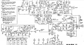
Mesa Mark II, schematic is posted below. This amp has been modified.
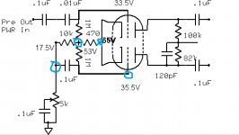
Also posted is a schematic I made to show where changes have been made to the circuit. In blue, are areas where the bottom half of the signal goes into a HF oscillation at a certain level of input signal, during oscilloscope probing.
Notes:
I tried changing power tubes and two different phase inverter tubes (ax7, at7).
Presence control affects the oscillation. At zero (pot value of zero across cap), the osc. rides about half the length or more of a 1khz test signal. As the presence control is turned to MAX, it squeezes the osc. up towards the front.
I am aware of the bias difference between the two tubes, and one side does clip before the other (the side without the osc.). Both 1M resistors measure exactly 1M (they are CC's) with the amp off.
I saw this same kind of thing happen two weeks ago on a Sears Silvertone. When I changed the power tubes on that amp, the asym. osc. went away completely. That amp did not have a NFB circuit or a Presence Control. I hope my test setup is not a factor here! I have isolated my scope and sig gen, along with the amp, to be sure.
Attachments
> aware of the bias difference between the two tubes
What bias difference?
Both grid readings are bogus and should not be taken literally.
When you put a 10Meg meter from the 1Meg to ground it meter-loads this stage very seriously. Obviously you can not have 55V-34V= 21V of bias on 12AX7/12AT7! If you have a second meter, watch the cathode as you meter each grid. The 55V is trustworthy. The "34V" are meter-loading multiplied by the self-bias action.
You are not clear if *this* amp has NFB. It would be real traditional here. Power tube series grid resistors also not clear. On factory amps it is not unknown to find 220pFd even 470pFd across both LTP plates (not just the one 120p you show). Also 5K to even 47K grid-stoppers at the 6L6/EL34s.
Thanks Ian and PRR.
I did some reading on Meter Loading. That was important for me to know and apply. If I got it right, the grid load resistor of 1Meg provides a self-biasing effect for the tube, using the small amount of positive current that is drawn through the resistor and into the grid, then into the cathode of the tube and completes the loop into the grid load resistor again. The value of the grid bias is "sensitive", because it is dependent on the 2 micro amps of current flowing in this loop. When I placed my 10Meg meter across the grid load, a new resistor was added in parallel, changing the flow of current in the grid load, and changing the voltage.
Where should I remember to apply the concept of meter loading? In other words, how do I identify a "sensitive" circuit? Is it the self biasing of ALL grid resistors, or is this example special in that the long tailed pair ALSO uses the cathode current to develop its bias voltage?
Back to the Amp, I have posted the schematic as a picture this time. It does have a NFB loop. the 10k and 56k resistors have been removed.
###I discovered something: The oscillation occurs when the load and scope are plugged into the 8OHM TAP, but NOT the 4OHM TAP. The NFB lead is attached to the 4ohm secondary tap, not to the 8ohm tap as in the diagram. The Slave output is still attached to the 8ohm as shown. The problem waveform has a frequency of 122.1kHz.
Attachments
> It does have a NFB loop. the 10k and 56k resistors have been removed.
Removed as in Open? Or removed as in Short?
If you tie the output with no resistance direct to the 5K Presence node, this scheme WILL oscillate supersonics. Also gain will be stunningly low. I'm not sure why anybody would do that to a guitar amp?
Assuming it does have a fairly traditional NFB network somehow...
> 8OHM TAP, but NOT the 4OHM TAP
> frequency of 122.1kHz.
Bah. We don't want 100+KHz. Put 100-300 pFd across the driver plates to roll-off the supersonic response. That's not the most elegant analysis but it usually works in guitar amps.
I'm going to remember the "caps across driver plate" idea for a rainy day.
Last night I removed the NFB wire from the 4-ohm tap and installed it on the 8-ohm tap, the same as in the schematic. The oscillation went away. Then, I had a power tube that went into some sort of "self-conduction" once it warmed up. After the amp was powered up and had about 5-10 minutes with a large signal, the current meter on my variac would begin to flutter. Then, this beautiful thing happened on the scope, one half of the waveform began to collapse - it looked like a massive drop in voltage and total compression of the signal while the current shot upwards until I shut down the amp. Replacing the power tubes restored the amp. Only one power tube had issues. It was drawing much more grid current than the others.
Thanks PRR
BTW, if you are still interested, when I say removed, technically, the 10k is a short (as the resistor is no longer "physically" in the circuit, and has been replaced with a conductor) and the 56k is open (as it has also been removed, and nothing has been replaced. So the .005 cap is in series with the conductor, on it's own). Essentially, there is no resistance in the FB loop.
I'm curious too as to why someone would modify the amp this way.
On the first input stage, the standard 1Meg Grid Load was swapped for a 220k - to lower the gain, right? Then, the phase inverter Grid Loads were increased 10 fold - to increase the gain, right? I've heard that phase inverter distortion has an important role in the tone and character of the distortion in an amp.
On the first input stage, the standard 1Meg Grid Load was swapped for a 220k - to lower the gain, right? Then, the phase inverter Grid Loads were increased 10 fold - to increase the gain, right? I've heard that phase inverter distortion has an important role in the tone and character of the distortion in an amp.
More important than lower the input impedance, lowering the grid resistor moves the frequency response of the amplifier, toward the higher frequency. In other words, if you maintain the same coupling cap, lowering the grid leak you loose bass or lower frequencies gain of the amp.
A 0.005u+5K NFB loop goes to unity gain above about 10KHz. Few power amps can stand unity-gain NFB. I think you "need" the 10K for stability. This may be conditional depending on load impedance, which on loudspeakers gets far above nominal impedance toward and past (122KHZ!) the audio band.
The amp will have a 10k reinstated in the Rf position. The modified phase inverter design was from the Marshall amp family. The amp is stable, but sounds "horribly dark", subjectively. I did some reading in my Fluke meter manual today. I have a 8060a True RMS, back from the 80's. The manual says that while it is a 10Meg standard input when configured for test normally, I have the ability to set it for ">100Meg Input", and ">1,000Meg Input" - as long as the meter never exceeds the standard Cat IV voltages and the tests last for fewer than 20 seconds when the DC/AC voltages are in excess of 300V. Sounds Great! This info is in regards to the "sensitive Phase Inverter Voltages" that we were talking about. Granted, the meter is still in parallel with the resistor under test, and the long-tailed pair isn't a critical scenario where it would be helpful to have a specific voltage (at the top of the tail resistor). What kind of circuitry would benefit from this extra input impedance? The Fluke 8060a also has a dB function.
The 8060a True RMS was designed specifically for Audio.
See: Old Fluke Multimeters - Page 1
See: Old Fluke Multimeters - Page 1
Not sure how well true RMS meters work with a clipped waveform.
And come to think of it, why are you mangling this great classic tube amp, anyway?
Sent from my LG-D801 using Tapatalk
Actually not true here. What you are referring to is grid leak biasing, which requires a much larger grid resistor and is only found in very, very old designs. The preamp stages in relatively more modern amps like this one, are cathode biased, and that grid resistor is simply ntended to hold the grid very close to zero volts. Placing a DVM across it will have no effect on the bias point.If I got it right, the grid load resistor of 1Meg provides a self-biasing effect for the tube, using the small amount of positive current that is drawn through the resistor and into the grid, then into the cathode of the tube and completes the loop into the grid load resistor again. The value of the grid bias is "sensitive", because it is dependent on the 2 micro amps of current flowing in this loop. When I placed my 10Meg meter across the grid load, a new resistor was added in parallel, changing the flow of current in the grid load, and changing the voltage.
And come to think of it, why are you mangling this great classic tube amp, anyway?
Sent from my LG-D801 using Tapatalk
Last edited:
- Status
- This old topic is closed. If you want to reopen this topic, contact a moderator using the "Report Post" button.
- Home
- Live Sound
- Instruments and Amps
- Asym oscillation BEFORE modified Phase Inverter in Mesa Mark II