Hi all,
I'm designing a medium/low gain guitar amplifier. Something that sits mostly in the clean to slightly overdriven sound. I have a question about reverb recovery and gain staging. Two general layout ideas are in the image attached.
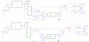
I'm using a 6GH8A pentode to drive a reverb tank, and the medium mu triode side for recovery. In idea 1 (top of the attachment), I have a parallel effects mixer a la Merlin's book using an entire 12AX7 tube (V3) feeding two paths: one un-reverbed signal that goes straight into another 12AX7 gain stage (V2B), and the reverb drive/recovery path which then resistor-mixes back into the same 12AX7 gain stage. However, I'm worried that the dry signal will overpower the reverb signal. A post by Merlin claims that the reverb tank output will be around 5mV RMS. If the 6GH8A triode has a gain of around 25, I'm optimistically looking at around 0.362Vpp of reverb signal.
An alternative idea (bottom of the attachment) is to use a parallel effects mixer a la AmpGarage user bluesfendermanblues that only uses one half of the 12AX7 (V3A), and to incorporate V3B as another recovery gain stage in series with the 6GH8A triode, and then back into the V2B 12AX7 driving the phase splitter. If V3B has a gain of 60, then I'm looking at close to 22Vpp of input into V2B - way too much?
Another option (not shown, but based on idea 1) is to switch V2B and V3B so the 12AX7 is in the recovery circuit and the 6GH8A drives the phase splitter.
Thoughts on these gain stage ideas? This is my first amp design, and I'm trying to get a grip on what the expected numbers are.
Thanks for your help.
Dave
I'm designing a medium/low gain guitar amplifier. Something that sits mostly in the clean to slightly overdriven sound. I have a question about reverb recovery and gain staging. Two general layout ideas are in the image attached.
I'm using a 6GH8A pentode to drive a reverb tank, and the medium mu triode side for recovery. In idea 1 (top of the attachment), I have a parallel effects mixer a la Merlin's book using an entire 12AX7 tube (V3) feeding two paths: one un-reverbed signal that goes straight into another 12AX7 gain stage (V2B), and the reverb drive/recovery path which then resistor-mixes back into the same 12AX7 gain stage. However, I'm worried that the dry signal will overpower the reverb signal. A post by Merlin claims that the reverb tank output will be around 5mV RMS. If the 6GH8A triode has a gain of around 25, I'm optimistically looking at around 0.362Vpp of reverb signal.
An alternative idea (bottom of the attachment) is to use a parallel effects mixer a la AmpGarage user bluesfendermanblues that only uses one half of the 12AX7 (V3A), and to incorporate V3B as another recovery gain stage in series with the 6GH8A triode, and then back into the V2B 12AX7 driving the phase splitter. If V3B has a gain of 60, then I'm looking at close to 22Vpp of input into V2B - way too much?
Another option (not shown, but based on idea 1) is to switch V2B and V3B so the 12AX7 is in the recovery circuit and the 6GH8A drives the phase splitter.
Thoughts on these gain stage ideas? This is my first amp design, and I'm trying to get a grip on what the expected numbers are.
Thanks for your help.
Dave
Attachments
Last edited:
 Guitar amp threads belong over in Instruments & Amps so I will move it.
Your drawing isn't detailed enough for me to advise in detail on.
Generally, you want the most gain in the first stage in order to keep noise minimal. By putting the master volume control at the input of the phase splitter, you get to turn down most of the noise (hiss and hum) from the input high gain stages (and guitar acting as an antenna) with the guitar level.
A pentode and a 12AX7 cascaded should give you enough gain. Even just two 12AX7's may be plenty. Most output stages don't give any real voltage gain since the transformer undoes what the output tube(s) do.
Reverb tanks vary a lot, and each one has certain requirements for drive level and gain needed on the output.
Keep all input wiring as far from the power supply and output stage as is practical. Almost every guitar amp ever made has a schematic on the web. Google "guitar amp schematics". I'd recommend studying those from Fender, Matchless, and others, and copying their tone stack circuits, if not the whole amp circuit, unless you have better ideas or want to experiment.
The Fender Deluxe is one of the most popular. It depends what you want for features and power rating, etc.
For reverb, unless you really want the authentic "spring" reverb for surf music, many digital processor pedals now do an amazing job of creating very lush reverbs. Most simulate spring reverb as well. The TC electronics HOF, or the Strymon, or the Neunaber are particularly notable, and these create optional stereo outputs which sound incredible.
In the power supply, build one that allows you to throw away roughly 50 volts of B+ with 2-3 sections of RC filtering after the retifiers, so you don't need to have a choke. And don't use a rectifier tube. It's a waste of space and energy. Use SS diodes and make sure to do the grounding right.
Tie all grounds in the power supply together, then run a wire from that junction to what will be the "star center" junction for all other ground connections (one from each stage generally), and let that also be the one place the circuit ground ties to the chassis ground. The earth ground green wire of the AC line cord should tie to the chassis separately, right where it enters the chassis.
Hammond transformers have always worked great for me, but you can buy "Fender" replacement output trannys for about half the price at Antique Electronics in AZ. I just recently built an amp using the Fender Deluxe output trannies which were about $35. It works great with either 6V6's or EL84's, to give you about 15 watts rms into 8 ohms.
If this is your first amp, I don't necessarily recommend doing a high power one.
I hope this helps.
Last edited:
Hey Bob,
Thank you for your advice and time - it's really appreciated. You're right, my diagrams were hastily drawn and might be confusing to look at. Their real purpose is just to show the position of gain stages in the amplifier. I'm using the pentode of a pentode-triode package to drive constant current into the reverb tank, and I'm debating between two layouts for the recovery:
1. Use the 6GH8A triode (gain = 25 ish) to recover the signal and resistively mix it into a 12AX7 before the PI. (Or, swap the 12AX7 and 6GH8A to get more voltage gain in the reverb recovery circuit).
2. Steal half of a 12AX7 from the parallel effects mixer and cascade it with the 6GH8A to get more voltage gain in the reverb recovery circuit. If it overwhelms the dry signal, I'll use local NFB to curb the gain of the cascaded tube.
One of my gripes as a first-time designer (planning before experimenting with the real thing) is dealing with apparently high signal voltages. For example, if I cascade the 6GH8A triode and a 12AX7 with gains of 25 and 60, respectively, and the reverb tank output is 5mV RMS, I'm going to get a 25Vpp signal. The input of a 12AX7 can only handle 3-4 Vpp, so won't I basically get a square wave? Without the cascade, I would have a 0.3 Vpp signal, which would probably be overwhelmed by the dry signal.
I have a couple of 5U4GBs floating around - I was going to make the amplifier have a tube rectifier using one of them. They have a fairly large plate resistance relative to some other tube rectifiers, which I figure will add a little bit of sag when the amp gets driven.
But you're right, without having to power that filament, I could get away with a smaller PT. And I suppose I could always use a series resistance with an SS rectifier to simulate sag.
As for the choke, I had also been planning on using one. I can get a high-inductance choke for around $20 near me, so cost isn't really an issue since 2-3 stages of 450V caps would cost nearly the same. Did you have another reason for suggesting I avoid a choke?
I don't have any personal experience with spring reverb circuits, so I can only advise generally on that. If I were to build one, I'd probably just copy one out of a known good amp.
Chokes add significant weight, besides taking up significant space. Carrying a guitar amp to gigs, and bending over to put it in my trunk, taught me to appreciate keeping the weight down any way I can. Chokes were cool when the biggest electrolytic caps you could get were 20-40uF. I consider them obsolete now.
Sag can be created with a simple RC, after the bigger RC's in the PS, so rectifier tubes are for those who don't get that.
A good rule of thumb is to not push a power tranny to more than about 75% of it's capability. When they saturate, they spew hum both through the wires and radiated through the air to nearby tubes. Plus they get hot, which ages them and nearby tubes faster.
Oh, and all filiment wires should be at least 18AWG solid strand so they stay put where you route them (not stranded), and twisted fairly tightly so their radiated hum will largely cancel out. Keep that wiring right against the chassis, and all other wiring up off the chassis. The more separation the better. Some amps put the filament wiring high up in the air, and all other wiring tight against the chassis. That works too but seems less practical.
Another great idea is to put a passive Rf filter right at the input of the amp. A 10k R in series and a 330p cap to gnd. will roll off the response above about 24kHZ, assuming the guitar pickup has about a 10k ohm source impedance (typical). Also put 10n 3KV ceramic caps across the AC inputs (hot and cold to earth ground), and on the secondary hi-V output of the power tranny. These will reduce noise and sputtering caused by light dimmers and the guitar acting as an antenna picking up all kinds of Rf crap in the air. Also switching noise from the diodes. For rectifier diodes, I use low noise fast recovery ones.
Hey Bob,
You're right, I may abandon the tube rectifier idea in favor of SS. It would make transformer selection easier and cut down on parts for filtering. A choke became necessary for me because the biggest reservoir cap you can use on a 5U4GB is 40uF, and in my simulations, I had a 10Vpp ripple at the plates - which might be fine when the CMRR of the push-pull output stage cancels it, but it certainly isn't good for the screens, even with an extra RC filter stage. With the SS rectifier, I can use a much larger reservoir cap and have a much smaller ripple at the plate.
I like your RC filter at the input idea. Should be simple enough, and it can be wired point to point since my ground star is going to be right at the input anyway.
I've made a few changes to my circuit that change the current draw, so I'm going to run some simulations using Hammond PTs. I'm also going to figure out if I can drop a PT size by cutting out the tube rectifier (saves about 15VA). I'll post an update about that later tonight.
Thanks!
Dave
The cancellation of CMRR in a push-pull output stage depends on the matching of the output tubes and balance of OT windings. Even so-called matched tubes are not likely matched at all levels, and even if they were, they change as they age.
Another trick I learned recently is to put a "zobal" filter across the speaker output. I use a 20 ohm 5W R in series with a .047 600V cap. It limits the impedance rise of the speaker, as seen by the OT. When a guitar amp is over driven into clipping, it generates a lot of high freq. energy, which will cause substantial ringing in the OT if the speaker load has gone way up in impedance (which it does). That ringing can cause arcing in some output tubes, which can then blow out the OT. Much like when the amp is operated without a speaker hooked up to it.
Another trick I learned recently is to put a "zobal" filter across the speaker output. I use a 20 ohm 5W R in series with a .047 600V cap. It limits the impedance rise of the speaker, as seen by the OT. When a guitar amp is over driven into clipping, it generates a lot of high freq. energy, which will cause substantial ringing in the OT if the speaker load has gone way up in impedance (which it does). That ringing can cause arcing in some output tubes, which can then blow out the OT. Much like when the amp is operated without a speaker hooked up to it.
- Status
- This old topic is closed. If you want to reopen this topic, contact a moderator using the "Report Post" button.
- Home
- Live Sound
- Instruments and Amps
- Gain Staging Ideas