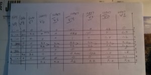
OK, that's better although those voltages are a little high but that seems to be the norm for these older amps. The -44,45 bias voltage seems a little high. You said they did the Blackface mod. Do you know if they also installed 1 ohm resistors in the cathode circuit for bias purposes? The best way to set bias is to know the current flow through the 6V6s instead of bias voltage. Look at pin 8 of the 6V6s and see if they go to ground or have resistors between them and ground. If they didn't, you might want to do this. Get some precision 1 ohm 1 watt resistors and put them between ground and pin 8. Also, do you still get the crackling noise?
It's OK to use carbon comps but if it is the plate load resistors, maybe metal film is better for the long run. It's up to you. Different people will think differently on this one. I've used carbon comps myself in the past with no problem.
It's OK to use carbon comps but if it is the plate load resistors, maybe metal film is better for the long run. It's up to you. Different people will think differently on this one. I've used carbon comps myself in the past with no problem.
Last edited:
Precision would be like 1% tolerance or better.
Did you replace the plate load resistors? Did you replace them with carbon composition resistors?
If you didn't replace the plate load resistors then do so with carbon film resistors. If you replaced them with Carbon Composition resistor then they can still crackle and pop.
Don't get too hung up on the 1 ohm "sensing resistors" at the cathodes of power tubes. Use your meter to read resistance and measure the DC resistance from center tap to each 6V6 plate from the output transformer. You can use this to determine how much current each 6V6's plate is conducting. Say you measured 100 ohms resistance from center tap to a plate (do this with no power). Then with power measure the voltage drop across said resistance, say it's 4 volts. Some basic math tells us that there is 40mA of current.
Remove tubes in order from preamp to power amp until the crackling goes away. This will tell you what section it is coming from. It could be a bad tube crackling and popping.
Precision would be like 1% tolerance or better.
Did you replace the plate load resistors? Did you replace them with carbon composition resistors?
If you didn't replace the plate load resistors then do so with carbon film resistors. If you replaced them with Carbon Composition resistor then they can still crackle and pop.
Don't get too hung up on the 1 ohm "sensing resistors" at the cathodes of power tubes. Use your meter to read resistance and measure the DC resistance from center tap to each 6V6 plate from the output transformer. You can use this to determine how much current each 6V6's plate is conducting. Say you measured 100 ohms resistance from center tap to a plate (do this with no power). Then with power measure the voltage drop across said resistance, say it's 4 volts. Some basic math tells us that there is 40mA of current.
Remove tubes in order from preamp to power amp until the crackling goes away. This will tell you what section it is coming from. It could be a bad tube crackling and popping.
I guess I suggested the 1 ohm resistors because you will be putting your meter on the highest voltages in the amp famousm'bird's way and you always need to do the math. With the 1 ohm resistor method, you use a voltmeter and because it is 1 ohm resistor, mV=mA, no math, no high voltage. I usually like to have people who are not really experienced with working on amps to use the cathode resistor method because you will be measuring the lowest voltages in the amp. Either way will work. Since you will be changing out resistors anyway, I thought it would be no big deal to do the 1 ohms also. You simply unsolder the wire going from pin 8 to ground and solder in a 1 ohm between ground and pin 8. Simple. You then measure the voltage across the resistor with power on. You use the mV setting on your meter. Your choice. But it is the best way to bias by finding the current in the 6V6s rather than just adjusting a bias voltage. I'm sure 'bird will agree with me on that. It all depends on if you are comfortable with measuring high voltages all the time when biasing.
I've seen the cables to the reverb unit go bad over time. That would be the first thing I'd look at. Crackle can be about any part, if it's not the cables. Large R's might be the next thing I'd try replacing. coupling caps that have large voltages across them next. I'd signal trace if possible.
I guess I suggested the 1 ohm resistors because you will be putting your meter on the highest voltages in the amp famousm'bird's way and you always need to do the math. With the 1 ohm resistor method, you use a voltmeter and because it is 1 ohm resistor, mV=mA, no math, no high voltage. I usually like to have people who are not really experienced with working on amps to use the cathode resistor method because you will be measuring the lowest voltages in the amp. Either way will work. Since you will be changing out resistors anyway, I thought it would be no big deal to do the 1 ohms also. You simply unsolder the wire going from pin 8 to ground and solder in a 1 ohm between ground and pin 8. Simple. You then measure the voltage across the resistor with power on. You use the mV setting on your meter. Your choice. But it is the best way to bias by finding the current in the 6V6s rather than just adjusting a bias voltage. I'm sure 'bird will agree with me on that. It all depends on if you are comfortable with measuring high voltages all the time when biasing.
True.
If it's your amp and you don't mind them there then everything is all good. If it isn't your amp and the person who owns it doesn't want them installed then I find doing it my way is easier and less invasive then soldering in 1 ohm resistors in series with the cathodes.
If the plate voltages are >300 I don't poke around while it's on. I hook my meter up appropriately then power up and take a measurement. Then I unplug and drain caps, change connections, power up again and take measurements. I use the suregrip alligator clip leads for my multimeter.
I do agree for novices the cathode resistor is much safer.
I soldered 1 ohm res to pin 8 of the 6v6's. I'm getting 1.16 ma for each of them. I also did the pull the tube thing and found that the AT7 at V6 as a problem. I replaced it with a nice JAN 12AT7 and it seemed fine for about 4 hours of playing through it. I used it to teach for about 4 hours and all of a sudden the volume jumped. :0( I started taping around the board and caps etc. with my chop-stick and found it to be very micro phonic across from V5-6-7. If I tap the chaise in that area it has pretty much the same effect.
I think I found it- there's a 47 ohm res across from the bass pot on the board was loose on the board. I replaced it with a new carbon film 1/2 watt and it seemed to do it.
Thanks so much for all your help on this. This amp gets to live another day!
For my next project- should I update my Heathkit tube tester or my Premier 90 Reverb? (it just buzzes)
Thanks so much for all your help on this. This amp gets to live another day!
For my next project- should I update my Heathkit tube tester or my Premier 90 Reverb? (it just buzzes)
Maybe you should measure the resistors to be sure they are 1 ohm. Do this with no power on the amp and drain filter caps.
Have you biased the amp the way you want it to be? 1.16mA for each tube is very cold bias. It should be around 18mA per tube. The 1 ohm resistor will make it easy. This is exactly why you installed it. Just set your meter to mV scale and adjust the bias so it reads about 18mV. 18mV=18mA.
Let's say you want them biased at 60%. 6V6s are rated for 14 watts. 14 watts x.6=8.4 watts. Now take 8.4 and divide by your voltage at pin 3. Based on your 452v from your rectifier tube, I would think you will have around 447v. 8.4 watts divided by 447 volts=18.8mA. So each 1 ohm resistor should have 18.8mV on your meter.
Last edited:
- Status
- This old topic is closed. If you want to reopen this topic, contact a moderator using the "Report Post" button.
- Home
- Live Sound
- Instruments and Amps
- Deluxe Reverb Silverface crackles and pops