JP you don't maybe have two of those fets for me? The only place I can source them here they are $2 each and I need to buy a minimum of 10, which is tight for a pensioner...
I am haveing a horrible three days... now on 3rd rebuild of a MXR dynacomp pedal... each with varying degrees of failure
Just came back from the printing shop with some press and peel for a third and final attempt... this time I went for 1.3mm traces and 1.3mm isolation... should be a bit more DIY friendly... there is quite a diffirence in designing a board for home etching and soldering and one that would come masked from a factory.
Hi can u help me???? please....
Please send me an e-mail at maniaxwanita@yahoo.com including the Jfet guitar preamp schematic of the page
www.bossaboa.dk/preamp.gif
because I don´t open this page from my home
Thank you very much
Please send me an e-mail at maniaxwanita@yahoo.com including the Jfet guitar preamp schematic of the page
www.bossaboa.dk/preamp.gif
because I don´t open this page from my home
Thank you very much
That site is closed, apparently. I get a "server does not exist" error message.
But if you want a nice FET preamp, this very thread has the best one I have found online, and I've done a LOT of searching. Plus it has a complete description of construction and the theory behind it as well.
Ken
But if you want a nice FET preamp, this very thread has the best one I have found online, and I've done a LOT of searching. Plus it has a complete description of construction and the theory behind it as well.
Ken
Re: Updated schematic for FET guitar preamp.....
I'm looking for a bass guitar preamp (a little bit more advanced than the one by Albert). If you have any ideas, please post them here.
Mark
The thread is quite interesting but I wonder which of the preamps were actually build and work correctly. In the schematic provided by Peter there is a mistake that will cause that the tone controls wont work; resitors R16, R17 and R18 should be connected to the output of U1B (which is how Albert Kreuzer's preamp is designed). Have you noticed this?jazzpeter65 said:Updated schematic for FET guitar preamp:
I've made a few adjustments and eratas since the first version.
This preamp sounds great - forget about opamps for a moment a try this one. It's warm, smooth and tubey. Very simple circuit with few phase invertion stages.
I'm looking for a bass guitar preamp (a little bit more advanced than the one by Albert). If you have any ideas, please post them here.
Mark
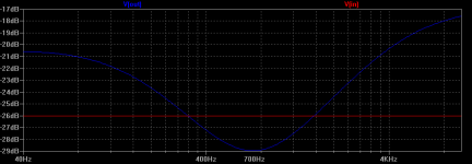
I also simulated one of the preamps mentioned in the begining of the thread; the Runoffgroove Cabsim. This is typical cabsim and I think that it shouldn't be used as a preamp (especially that it has gain < 1). Attached is frequency response of the cabsim.
Mark
Mark
Attachments
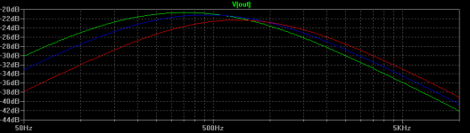
I simulated the preamp. Attached is the frequency plot of the preamp. Looks good but I'm worried about two issues; the gain changes with the frequency and it's x1.8 at low frequencies and x2.5 (and not x6.5 as mentioned in one of previous posts), and other issue it that it's quite difficult to buy J201 (with other transistors I get much lower gain).
But still it looks interesting.
Mark
But still it looks interesting.
Mark
Attachments
JFET Guitar Preamp
Hi Mark,
The surface mount JFET I used in the circuit shown in my picture was actually a surplus Interfet device that is similar in specification to the Interfet SMP4867. There are certainly other JFETs you could use but remember, if you plan on using a JFET as an amplifier in an "on-board" circuit with a 9.0 Volt battery, there are definite limitations to power-draw and headroom.
I have said many times that the J201 is not a "magic" device, other devices that can be used are the Toshiba 2SK170 and the 2N5457 (provided that the devices chosen are on the "low-end" of thier specification scale). However, to function properly in the self-bias "Hugsley" circuit described in my previous postings, the 2SK170 and 2N5457 may have to be "screend" for an optimal fit.
If you have other JFETs you would like to try then, by all means, feel free to try them (preferably ones with characteristics similar to the J201). If you bias them up in thier optimal linear region as described in my previous postings, then I'm pretty sure you will have a viable circuit.
I hope this helps,
JP Hugsley
Thanks for the answer. At the moment I'm only simulating the preamp in Spice. And when I change J201 to other FETs, gain drops down - the transistor is definitely incorrectly biased.
BTW, I'm looking for similar preamp for bass guitar. You mentioned that it is based on Fender. Which Fender model did you mean, Bassman 135? It seems that for bass guitar you need different components. Especially that the Mid frequency minimum is at much lower frequency. With your preamp the minimum is at 700Hz and with Fender it's below 400Hz. Do you have a set of components for bass guitar? Or you advise me to use just the components from Bassman 135?
Mark
JFET Guitar Preamp
Hi Mark,
The EQ used in the Hugsley preamp is a generic topology that Fender used for many of thier early tube designs. This topology was "standard" on many of the RCA Tube Manual public domain schematics for preamplfiers in the fifties and sixties.
The values I used for the Hugsley preamp were scaled to more-or-less 1/2 the resistance values and 2 times the capacitor values of some of the "classic" Fender designs; e.g. the Bassman, Bandmaster and Deluxe Reverb (this was done because the drain resistor of the J201 was roughly 1/2 the value of the standard Fender 12AX7 plate resistor).
If you have Spice, I suggest that you simulate the EQ's that you actually like and then use the resistance and capacitance values based on thoses simulations. After that, construct the EQ's and spend some time listening to the different "tonal" configurations.
The best advice I can give you is to listen and re-configure the EQ's until you converge on a set of values you like best.
Remeber, in the design of guitar preamps (including bass guitars), the Spice simulations are an excellent tool to help you in the development of a design but, ultimately, it's your ears that will have the final say.
Have fun!
JP Hugsley
RCA and other manufacturers have always published what are called "reference designs". National Semiconductor and other manufacturers still do this. they are the designs in App Notes and data sheets. for instance RCA's color TV reference design waas the basis for untold millions of TV's manufactured in the 50's, 60's and even into the '70's. a reference design is a starting place, and is left up to the individual engineer to improve upon. some manufacturers like Fender will use a reference design as part of something else (such as a guitar amp, when the RCA book had it as part of a home stereo amp). we do the same things today when we take a NatSemi 3 band EQ/tone control, and tweak it for a particular project. some reference designs may have patents attached to them, but most probably do not. Western Electric (Bell Labs) got into a big battle with experimenters who published in magazines such as Radio-Electronics, when the magazines published articles about using LED's as photo detectors. Bell Labs had a "brainstorming" patent, where they patented EVERY conceivable future use of an LED, and expected EVERYBODY who designed anything using LED's to pay licensing fees.
i don't think their patent held up in court, because EVERYBODY is making devices with LED's. Bell took a writer for Radio-Electronics to court for publishing an article about LED's as photodiodes. i don't remember the exact outcome, but i do know the writer was later allowed to continue.
i don't think their patent held up in court, because EVERYBODY is making devices with LED's. Bell took a writer for Radio-Electronics to court for publishing an article about LED's as photodiodes. i don't remember the exact outcome, but i do know the writer was later allowed to continue.
Unclejed,
This is interesting. I was lately trying to fix a bass guitar active preamp (which was developed using most probably the NatSemi 3 band EQ reference design, like the one here: http://www.diyaudio.com/forums/showthread.php?threadid=92121). I run Spice simulations of the circuitry and found out that the reason for poor sound was that "the mids are affected by the relative position of the other two....so there isn't a mid control per se." - exactly what was mentioned in the other thread. Turning up mids was influencing the high frequency filter. And the problem was caused by the design of the preamp. The best solution was not to use the mids pot .
.
Mark
This is interesting. I was lately trying to fix a bass guitar active preamp (which was developed using most probably the NatSemi 3 band EQ reference design, like the one here: http://www.diyaudio.com/forums/showthread.php?threadid=92121). I run Spice simulations of the circuitry and found out that the reason for poor sound was that "the mids are affected by the relative position of the other two....so there isn't a mid control per se." - exactly what was mentioned in the other thread. Turning up mids was influencing the high frequency filter. And the problem was caused by the design of the preamp. The best solution was not to use the mids pot
.Mark
Dear mr. Hugsley (or anyone),
I have two piezo brigdes that I want to build preamps for (I tried wiring up the Tillman, but all J2O1's I have biased around 8V (drain to ground), so I need to modify somehow); how would I go about measuring the impedance of the piezos, so I can wire up a perfect match?
Thanks in advance,
/Tomas
I have two piezo brigdes that I want to build preamps for (I tried wiring up the Tillman, but all J2O1's I have biased around 8V (drain to ground), so I need to modify somehow); how would I go about measuring the impedance of the piezos, so I can wire up a perfect match?
Thanks in advance,
/Tomas
Tomas,Originally posted by cernael I have two piezo brigdes that I want to build preamps for (I tried wiring up the Tillman, but all J2O1's I have biased around 8V (drain to ground), so I need to modify somehow); how would I go about measuring the impedance of the piezos, so I can wire up a perfect match?
Tomas
The 8V voltage on the drain in Tillman's preamp seems to be OK (with 9V power supply). But still the preamp should work with piezo. Have you tried it?
Mr. Hugsley's preamp should also work but it contains a filter, which I'm not sure whether it's going to sound good with piezo.
Here: http://www.carvinmuseum.com/pdf/guitarbass/506p-activepiezobassmodule.pdf you can find a schematic for piezo+magnetic pickups preamp for bass guitar. I think it can be adjusted for a guitar piezo.
Mark
- Status
- This old topic is closed. If you want to reopen this topic, contact a moderator using the "Report Post" button.
- Home
- Live Sound
- Instruments and Amps
- New JFET guitar preamp project