Hi everyone,
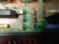
I've received a Hughes and Keittner Attax 100 guitar amp that is blowing 2A fuse when the speaker or 8ohm load connected.
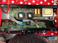
I powered up the amp on my work bench with an isolation transformer and variac with a 100watt lamp in series as a current limiter. On first power up the lamp lit bright. I removed the power and checked around the power board testing resistor values, checking diodes, and checking caps for ESR and values. Some caps are away off value but esr are ok.
There is no short at the speaker out connection when powered off.
I have not removed the MJ4035 and MJ4032 transistors from the board yet to test as I thought I would seek some advice before disturbing anything.
I would be greatful if someone out there could lend me a hand to repair this amp.
I have attached some pictures
Many thanks
Paul
I've received a Hughes and Keittner Attax 100 guitar amp that is blowing 2A fuse when the speaker or 8ohm load connected.
I powered up the amp on my work bench with an isolation transformer and variac with a 100watt lamp in series as a current limiter. On first power up the lamp lit bright. I removed the power and checked around the power board testing resistor values, checking diodes, and checking caps for ESR and values. Some caps are away off value but esr are ok.
There is no short at the speaker out connection when powered off.
I have not removed the MJ4035 and MJ4032 transistors from the board yet to test as I thought I would seek some advice before disturbing anything.
I would be greatful if someone out there could lend me a hand to repair this amp.
I have attached some pictures
Many thanks
Paul
Attachments
Agree, in such case *first* suspects are shorted power transistors; next in line (far behind) is a shorted main rectifier bridge.
Try to get the schematic and post or link it here so we all talk same part numbers.
Or straight ask it from H&K .
Maybe they don't want it on the Net, but you might scan and crop just the relevant part, say the power amp without preamps, supply, effects or switching, and that would qualify as "fair use", in this case getting help from fellow Techs for a real needed repair.
As of large heavy filter caps falling from PCBs, is something happening everywhere (including Fender, Peavey, etc.) because wave soldering is way too much efficient and leaves the minimum amount possible of solder , and modern lead free solder is brittle, easy to crack under vibration and stress.
Last edited:
I have finally hot around to getting a look at this amp sorry for delay in replying.
I removed T9 and T10 from the pcb. I noticed the thermal paste on these transistors had gone brittle and crumbled apart on removal..
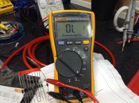
I measured on diode setting using my fluke 115 between B & C and got no shorts on these ..
T9 MJ4035 black probe to base and red on collector (case) = no short Open.
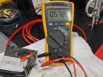
Red probe to base and black on collector (case ) = 0.586 ohms
Red on base and black on emitter = 0.617 Ohms
Black on base red on emitter = 1.625 Ohms
Black on collector, Red on emitter = 0.466 Ohms
Red on collector, Black on emitter = Open
T10 MJ4042 Black on B / Red on C = 0.586 ohms
Red on B / Black on C = Open.
Red on B / Black on E = 1.442 Ohms
Black on B / Red on E = 0.615 Ohms.
Black on C / Red on E = Open.
Red on C / Black on E 0.504 Ohms.
T6, T7, T8, all tested good on board. No shorts.
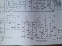
I have attached a schematic of the Attax 100 power amp section.
I have cleaned of the old paste on these power transistors with Isoproply alcohol cleaner ready to be refitted with new paste.
I removed the legs of C64 and C65 big smothing caps and measured them individualy on the peak ESR meter. They both read good with .02 ESR values. I cleaned the board here and resoldered.
I removed the bridge rectifier and tested it using analogue meter. My procedure is - Set to x 10K ohms red to + and black to one of the ~ pins. I got a high reading. Reversing the probes - no reading. Placing black probe to negitave and red to the other ~ pin ... Showed a reading. Reversing did not show a reading. Measuring between ~ pins should had no continuity. All good here. Cleaned solder traces and soldered back to board.
I will test all the values of resistors and compare them to the schematic and test all caps.
After that plan I'm thinking of re inserting T9 and T10 and start looking at powering it up again and checking voltages voltages.
Thanks
I removed T9 and T10 from the pcb. I noticed the thermal paste on these transistors had gone brittle and crumbled apart on removal..
I measured on diode setting using my fluke 115 between B & C and got no shorts on these ..
T9 MJ4035 black probe to base and red on collector (case) = no short Open.
Red probe to base and black on collector (case ) = 0.586 ohms
Red on base and black on emitter = 0.617 Ohms
Black on base red on emitter = 1.625 Ohms
Black on collector, Red on emitter = 0.466 Ohms
Red on collector, Black on emitter = Open
T10 MJ4042 Black on B / Red on C = 0.586 ohms
Red on B / Black on C = Open.
Red on B / Black on E = 1.442 Ohms
Black on B / Red on E = 0.615 Ohms.
Black on C / Red on E = Open.
Red on C / Black on E 0.504 Ohms.
T6, T7, T8, all tested good on board. No shorts.
I have attached a schematic of the Attax 100 power amp section.
I have cleaned of the old paste on these power transistors with Isoproply alcohol cleaner ready to be refitted with new paste.
I removed the legs of C64 and C65 big smothing caps and measured them individualy on the peak ESR meter. They both read good with .02 ESR values. I cleaned the board here and resoldered.
I removed the bridge rectifier and tested it using analogue meter. My procedure is - Set to x 10K ohms red to + and black to one of the ~ pins. I got a high reading. Reversing the probes - no reading. Placing black probe to negitave and red to the other ~ pin ... Showed a reading. Reversing did not show a reading. Measuring between ~ pins should had no continuity. All good here. Cleaned solder traces and soldered back to board.
I will test all the values of resistors and compare them to the schematic and test all caps.
After that plan I'm thinking of re inserting T9 and T10 and start looking at powering it up again and checking voltages voltages.
Thanks
Attachments
Ok, then power transistors still remain at the head of the suspect list.
Please recheck each all ways (6 readings in total for each transistor) using the diode test scale.
What you will read is millivolts drop across junctions, not ohms resistance .
values.
Just to be certain we are talking the same, please also measure both ways and post results found when testing a generic diode (a 1N400x type will be fine).
EDIT: to save time, also measure DC voltage across (C to E) bias transistor T6 .
I expect around 2.5V to 3V DC
Last edited:
Using the diode test scale I've tested a regular N4007 diode.
Forward bias test - red probe to cathode, black prob to anode = 0.568v
reverse bias test - red probe to anode, black to cathode Open.
Testing T9
B-E
positive lead to Base & negative lead to the Emitter = 0.626v
Negative lead to Base & Positive to Emitter = 1.616v
B-C
Positive lead to Base & Negative lead to Collector = 0.602v
Negative lead to Base & Positive lead to collector = Open
E-C
Positive lead to emitter & Negative to collector = 0.469v
Negative lead to emitter & positive to collector = Open.
Testing T10
B-E
positive lead to Base & negative lead to the Emitter = 1.443v (should be open?)
Negative lead to Base & Positive to Emitter = 0.614v
B-C
Positive lead to Base & Negative lead to Collector = Open
Negative lead to Base & Positive lead to collector = 0.592v
E-C
Positive lead to emitter & Negative to collector = Open
Negative lead to emitter & positive to collector = 0.502v
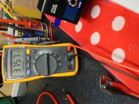
DC voltage across (C to E ) bias transistor T 6 = 1.8v
Forward bias test - red probe to cathode, black prob to anode = 0.568v
reverse bias test - red probe to anode, black to cathode Open.
Testing T9
B-E
positive lead to Base & negative lead to the Emitter = 0.626v
Negative lead to Base & Positive to Emitter = 1.616v
B-C
Positive lead to Base & Negative lead to Collector = 0.602v
Negative lead to Base & Positive lead to collector = Open
E-C
Positive lead to emitter & Negative to collector = 0.469v
Negative lead to emitter & positive to collector = Open.
Testing T10
B-E
positive lead to Base & negative lead to the Emitter = 1.443v (should be open?)
Negative lead to Base & Positive to Emitter = 0.614v
B-C
Positive lead to Base & Negative lead to Collector = Open
Negative lead to Base & Positive lead to collector = 0.592v
E-C
Positive lead to emitter & Negative to collector = Open
Negative lead to emitter & positive to collector = 0.502v
DC voltage across (C to E ) bias transistor T 6 = 1.8v
Attachments
These values sound reasonable and point to working T9 and T10.Using the diode test scale I've tested a regular N4007 diode.
Forward bias test - red probe to cathode, black prob to anode = 0.568v
reverse bias test - red probe to anode, black to cathode Open.
Testing T9
B-E
positive lead to Base & negative lead to the Emitter = 0.626v OK
Negative lead to Base & Positive to Emitter = 1.616v repeat on an ohm scale, darlingtons include an approximately 1k resistor base to emitter so test on the 2k scale.
B-C
Positive lead to Base & Negative lead to Collector = 0.602v OK
Negative lead to Base & Positive lead to collector = Open OK
E-C
Positive lead to emitter & Negative to collector = 0.469v OK
Negative lead to emitter & positive to collector = Open. OK
Testing T10
B-E
positive lead to Base & negative lead to the Emitter = 1.443v (should be open?) it might be the internal resistor I mentioned above, repeat on the 2k ohms scale
Negative lead to Base & Positive to Emitter = 0.614v OK
B-C
Positive lead to Base & Negative lead to Collector = Open OK
Negative lead to Base & Positive lead to collector = 0.592v OK
E-C
Positive lead to emitter & Negative to collector = Open OK
Negative lead to emitter & positive to collector = 0.502v OK
DC voltage across (C to E ) bias transistor T 6 = 1.8v OK
I'd clean them and the heatsink well (your cloth wet with isopropyl alcohol is fine), re mount them carefully, with micas and grease , and check that collectors (case) are not grounded.
I know they use those cheesy star shaped sinks, but they *might* have some mounting clips , fingers or screws which ground them, so recheck transistor case non grounding.
After that, just in case, short T6 (bias) C-E with a short wire, we'll worry about bias later.
Then turn amp on, without speaker or any load, through the lamp limiting bulb.
How does it react? (use a 50 to 100W one, 60/75W is fine).
Measure rails voltage and speaker out DC too.
Obviously no signal, all controls on 0, etc.
I forgot: check that the ballast emitter resistors R158/159 are still alive.
Remember to short meter probes before measuring and substracting that value from display reading.
Last edited:
T9
Negative lead to Base & Positive to Emitter = 5.119 ohms
T10
Negative lead to Base & Positive to Emitter = 3.764 ohms
(I used the auto range on my fluke 115 multimeter to measure all ohms values )
ballast emitter resistor R158
Leads 0.1 - 0.3 = 0.2 ohms
ballast emitter resistor R159
Leads 0.1- 0.3 = 0.2 ohms
I will start re installing T9 & T10
Attachments
Re installed T9 and T10
Shortened out T6 C-E with short wire
No load connected & No signal connected.
Powered on slowly with variac and lamp current limiter (100w) - all ok, no light from current limiter.
Measured DC voltage at speaker out = 0v
Measured after being on for 20m still 0V
Measured DC rail voltage 45.75v & - 45.63v
I had to use the hold function on the metre to get a settled reading after the decimal point.
All seems ok
*IF* biasing transistor T6 is open output transistors T9 and T10 will be FULLY turned on, and both at the same time, so they will behave like they are shorted ... even if they are fine.
Fuse will blow (or lamp will shine bright killing rails) , you want to smash the amp with a sledgehammer, so shorting T6 is a useful step during troubleshooting, we momentarily get rid of a troublemaker.
Go ahead, connect the speaker (still with lamp limiter in the way) , play a few chords at low volume, 1 or 2 watts.
It will have some buzzy sound in the background because of crossover distortion, no big deal.
You may have to turn amp on first without load, then connect speaker, some amps "wake up stupid" if fed through a lamp limiter and can't handle a speaker at turn on.
If everything seems fine, repeat but previously unshorting T6.
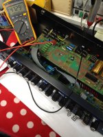
I decided to mount the power board into the amp and secure to the chassis. I powered on with lamp limiter and no load. I was surprised to find no voltage on the + - rails. I checked at other points on the board and found no voltage. I check voltages across big smoothing caps and got no voltage. This had me puzzled. I removed the power board from the chasis again and tested on a block of wood. Measured voltages - All back on ..I started to investigate and found one leg of the transformer broken connecting to the PCB. I repaired this and strengthened the solder joints on rest of tx connections. (A heavy piece of metal on any board).
Mounted power board back on chasis and powered on. All ok.
Attached load ( 500w 8 ohm resistor ) - all ok.
Attached input signal ( 1khz sine wave 600 mV) watched output on scope.
Attached input CD player - with output speaker - all ok.
Removed short wire from T6 C-E.
Ran all tests again. All ok.
Next tests I will try without lamp limiter in circuit
Will this amp need to be biased? And would it be fair to say all is ok? I ran the amp for half an hour with lamp limiter in place at a low volume. I will do the same test tonight without the limiter in place. Maybe run it for a bit longer.
- Status
- This old topic is closed. If you want to reopen this topic, contact a moderator using the "Report Post" button.
- Home
- Live Sound
- Instruments and Amps
- Hughes and Keittner Attax 100 blowing fuse