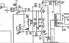
I have this Music Man that I am trying to get the bias correct with a pair of brand new Electro Harmonix 6CA7EH's. I have the bias maxed and I am only getting 17mV and 20mV across the emitter resistors, to make matters worse the emitter resistors measure high, 4R4.......4mA isn't enough, I am looking for at least 10mA I think. The service manual says a minimum of 25mV and a maximum of 55mV across the 3R9 emitter resistors. I am thinking of adding another 1N4005 diode in series so the pot can sweep from 600mV to 1.7mV. I attached a pic of my mod along with the service manual, if anyone can tell me if this won't work or why I shouldn't do it that would be great I am no engineer but I think my proposed mod should work to get the current up throught the power tubes, I just don't want to blow anything up lol.
It has the GP-3 board in it.
Thanks
-bird
I am no engineer but I think my proposed mod should work to get the current up throught the power tubes, I just don't want to blow anything up lol. It has the GP-3 board in it.
Thanks
-bird
Attachments
First, how does the amp sound?
Your method would probably expand the adjustment range, but I have never seen a MM amp that needed such modification. These amps run close to class B, so there is very low idle current. COnsider the recommended range of 25mv to 55mv. I will just call that about 30ma as an average. 30ma through 3.9 ohms is only about 7ma of tube current. You are getting only 20ma, or 5ma, not much difference. Even at the top of the range at 55mv, that is still only 14ma of tube current. Or put another way, 20mv is only 20% out of range. Old Fender schematics always had a note that all readings were +/-20%, I liked that.
Your 3.9 ohms measure 4.4. Half an ohm? OK, short your probe tips together and see how much resistance they have, then subtract that from your readings. That will get the real resistance. Also, never hurts to reverse your leads and remeasure just in case there is some tiny residual voltage left in the circuit. That would affect readings. And another small factor. I can't imagine the resistors are tighter tolerance than 5%, and 10% would not be surprising. 5% of 3.9 ohms is about 0.2 ohms, so there is some additional bits of an ohm to work within.
Looking elsewhere, your grids are biased to +22v by the zener D7. Is that voltage up to level? If that zene is collapsing, the grid voltage could sink and the tubes would be driven less hard, which would explain both sides running cool. Since both sides seem to be running alike, I doubt you have bad transistors.
I personally think your mod is unnecessary, but as to blowing anything up, your tubes are not idling hot, and look at how the circuit works. Mod or no mod, at the bottom of the control setting the transistor base bias is one diode drop above ground. If you add a diode to increase the top end, that doesn't alter the bottom end, right? SO if you DO do this, just set it at the cold end first and watch as you adjust.
Hello Enzo, I have not got around to hooking it up to a speaker yet so I am not sure how it sounds. I was also going to look at it on a scope to see if I can see any crossover distortion, if I see the crossover distortion then I might implement the mod. I remember reading on another forum that these amps sound much better when you get closer to the 55mV bias. Anyway I think when I get the time to put it on a scope and see what the output looks like is when I will make the decision of what to do. I just wanted to make sure what I had in mind was the best way to do it, like you said the bottom will be the same which is one diode drop above ground, my mod should just give me more of an adjustment range. If anything the voltage drop across the 3.3k resistor goes down which will decrease the current through it, resistor rating there doesn't have to change me thinks.
I hope you at least have it on a load. You should NEVER operate a tube amp without a load. Ther is often crossover distortion in tube guitar amps. A few percents of it go unheard, and the amps are far from hifi by design anyway.
Use Ohm's Law, the 3.3k has about 45v across it if the diodes are a dead short, and that dissipates about 0.6 watts. Reducing the voltage drop by a half a volt will not make a difference. It is a 2w resistor.
Someone may think it sounds better with the tubes running as hot as possible. Someone always thinks that no matter what amp we discuss. But everyone's idea of "better" is a matter of taste, and also it matters a great deal how the amp is used. The whole point of the amp is to make good sounds, so the most important test there is is your ear. So I urge you to listen to the amp before deciding to do anything to it. All the scoping and measuring in the world will not tell you what it sounds like.
Agree and add: I'm sure the amp is working properly and will sound killer, like all Musicman do by the way, don't psychologically convince yourself that something is wrong after checking those readings and then actually thinking it sounds bad, because it will not.
And running hotter or colder may have some meaning in simple conventional amps, but here constant current is force injected into cathodes, whether they like it or not, by Op Amp and transistor controlled current sources.
A very clever circuit which pushes tubes to maximum power possible.
And running hotter or colder may have some meaning in simple conventional amps, but here constant current is force injected into cathodes, whether they like it or not, by Op Amp and transistor controlled current sources.
A very clever circuit which pushes tubes to maximum power possible.
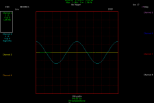
Hey guys output looks good to me, attached is an image at full output. I am going to hook it up to some speakers, I am sure it will sound good.
Are there any Hi-Fi guys using this grounded grid topology for finals? Seems like a nice way to squeak max power from tubes and still run them cool. Real life is different but I am probably going to run some simulations to see how it can perform. The only thing the web turned up was for RF amplification.
Are there any Hi-Fi guys using this grounded grid topology for finals? Seems like a nice way to squeak max power from tubes and still run them cool. Real life is different but I am probably going to run some simulations to see how it can perform. The only thing the web turned up was for RF amplification.
Attachments
Okay so I noticed that the chassis is stamped with 100 watts RMS output. I am only getting 65 watts This amp has two 6CA7's. I noticed in the service manual there is a 65 watt and 100 watt models. What is the difference? I would think that the 65 watt model has two power tubes and the 100 watt model has 4? Sorry I am not familiar with the Music Man amps.
This amp has two 6CA7's. I noticed in the service manual there is a 65 watt and 100 watt models. What is the difference? I would think that the 65 watt model has two power tubes and the 100 watt model has 4? Sorry I am not familiar with the Music Man amps.This thing had no tubes in it when my buddy brought it to me. He is only here visiting and is leaving in a couple days. I think the amp is fine, it sounds good. But now that I have done some diggin on the interwebs I should have put 6L6GC's in it It seems like their models that have two 6CA7's put out 65 watts (what I am getting) and the ones with 6L6's put out 100. Two reasons I put the 6CA7's in the amp was because the schematic had them and the maximum plate voltage rating was higher for the 6CA7's. I know the cathode isn't at ground potential but the 6L6 max plate voltage rating would still be compramised.
It seems like their models that have two 6CA7's put out 65 watts (what I am getting) and the ones with 6L6's put out 100. Two reasons I put the 6CA7's in the amp was because the schematic had them and the maximum plate voltage rating was higher for the 6CA7's. I know the cathode isn't at ground potential but the 6L6 max plate voltage rating would still be compramised.Short answer: 2 tubes 65W RS (which is a LOT), 4 tubes "130W RMS" although they might have made a less turbocharged one with "only" 100W RMS.Okay so I noticed that the chassis is stamped with 100 watts RMS output. I am only getting 65 watts
They are famous for loud and clean, now you know why
Digging up an old thread of mine to pick the brains on here. Short story is I was going to build myself a hifi preamp for a project this fall and winter but a McIntosh C20 fell in my lap for a good price so I grabbed it. Now I need a new project idea. I was toying with the idea of building a power amp. The Musicman amps are powerful and clean, I really dig the sound. What are the benefits of running the output stage common grid? I thought it was just for RF? It's late here and I am amp dreaming before bed but to me it looks like the signal goes through half an inverting stage of an opamp with a 100k feedback resistor, which feeds half the output stage and the other half of an inverting opamp stage with a 10k feedback resistor and the other half of the output stage. Kinda like a paraphase inverter. Now the transistors are there to drive the cathodes as they are a tough load. I will dig out the books and sim software but how does the amp get away with such little bias current and still put out a clean output without crossover distortion? Why don't other companies do this? Seems like a great way to get lots of power with low current, tubes should last a long time. I may be able to figure out how it works with a lot of head scratching and thinking but I am sure someone can explain it easy to me and save me some time. It just seems like a great way to make gobs of clean power and not replace power tubes every couple years. I have never heard one clip so maybe they don't clip pleasantly? Still could be good for hifi but I never see similar designs in hifi either. Weird and intriguing design.........I like it.
Please, I welcome all comments and insight. Thank you.
Please, I welcome all comments and insight. Thank you.
Idle current is low because these are biased very close to class B.
Signal enters the first op amp, gets a little gain, and is applied to the upper tube drive. Your 10k/10k second op amp is just a unity gain buffer that inverts the signal. SO whatever is fed to the upper tube drive causes the lower tube drive to send the exact same signal but inverted.
Why don't other companies to this? Well, Peavey already did, and as far as I know before Music Man did. Any of the Peavey VTX series amps are cathode drive. Classic, Heritage, and seems to me a couple others.
But mainly, they don't do it because they don't need to. It adds complexity, and amps have no trouble cranking out 100 watts or more from a quad of tubes the old fashioned way, and getting a handful more watts will not be any louder really.
I don't generally look to guitar amps for hifi signals. Guitar amps are by design meant to color the sound.
(Quote truncated).........common grid?
The grid swing of the tube is 50V.
The base swing of the transistor could be 50mV.
By putting a large emitter resistor under, the swing may be 5V but the 100:1 degeneration means the gain is constant down to very low current (bias).
The "tube input" (now an NPN) may be DC coupled (I don't think all MMs did this) for less grid-blocking.
It approaches a transistor amplifier except the heavy work is done by tubes. At the time tubes were perhaps more reliable in stage abuse, and could be replaced quick and cheap.
- Status
- This old topic is closed. If you want to reopen this topic, contact a moderator using the "Report Post" button.
- Home
- Live Sound
- Instruments and Amps
- Music Man GP-3 Bias