Hi there, I'm interested in making a microphone tube preamp that also has a built in limiter/compressor so there's little difference between loud and quiet sounds. Designing and making a tube preamp that can drive a relatively low-impedance input such as a computer's line-in is easy enough, I can pretty much do that in my sleep.
Trouble is I want to add a compressor to the preamp, but the only schematics I can find either require a LOT of tubes or have a very high output impedance meaning that I cannot connect it to most of the stuff I have.
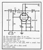
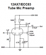
I tried one schematic for a compressor (the one that's on the very left), but again this is one of the ones that has a ridiculously high output impedance and I couldn't get it to work anyway, I thought I could connect it to the output of my preamp but like I said it was a no-go. Also I've attached a schematic of my preamp.
Another compressor I found uses a pentode with what appears to have the third grid "modulated" to adjust the gain. What about that? Would that work?
So can anyone direct me to a schematic that can amplify a microphone, uses standard tubes that most tube nuts like my self would have (such as the ECC83/12AX7), has a built in limiter and has a reasonably low-impedance output (100k or less)?
any help on that would be appreciated.
Trouble is I want to add a compressor to the preamp, but the only schematics I can find either require a LOT of tubes or have a very high output impedance meaning that I cannot connect it to most of the stuff I have.
I tried one schematic for a compressor (the one that's on the very left), but again this is one of the ones that has a ridiculously high output impedance and I couldn't get it to work anyway, I thought I could connect it to the output of my preamp but like I said it was a no-go. Also I've attached a schematic of my preamp.
Another compressor I found uses a pentode with what appears to have the third grid "modulated" to adjust the gain. What about that? Would that work?
So can anyone direct me to a schematic that can amplify a microphone, uses standard tubes that most tube nuts like my self would have (such as the ECC83/12AX7), has a built in limiter and has a reasonably low-impedance output (100k or less)?
any help on that would be appreciated.
Attachments
For the lowest tube count I would recommend using an opto resistor as the gain controlling element. There are plenty available with built in LEDs.
Here's a link to a two tube design:
http://www.ianbell.ukfsn.org/EzTubeMixer/docs/PMTCL/PMTCLsc.jpeg
Cheers
Ian
Here's a link to a two tube design:
http://www.ianbell.ukfsn.org/EzTubeMixer/docs/PMTCL/PMTCLsc.jpeg
Cheers
Ian
For the lowest tube count I would recommend using an opto resistor as the gain controlling element. There are plenty available with built in LEDs.
Here's a link to a two tube design:
http://www.ianbell.ukfsn.org/EzTubeMixer/docs/PMTCL/PMTCLsc.jpeg
Nice diagram. Ambiguous penmanship! The cathode-bypass capacitor on the rightmost tube… is that 220 nF or 220 μF? could be that old 'μ' symbol, you know. … … granted which 95% of everyone have long given up using, but still.
GoatGuy
Nice diagram. Ambiguous penmanship! The cathode-bypass capacitor on the rightmost tube… is that 220 nF or 220 μF? could be that old 'μ' symbol, you know. … … granted which 95% of everyone have long given up using, but still.
GoatGuy
Ah, I see what you mean. You think my μ looks like a capital N - which would of course be quite wrong for nano-Farads.
Can't understand why engineers and electronics hobbyists would have given up using the μ for micro. Probably the advent of keyboards and business oriented software that made access to technical symbols such a chore.
Cheers
Ian
For the lowest tube count I would recommend using an opto resistor as the gain controlling element. There are plenty available with built in LEDs.
Here's a link to a two tube design:
http://www.ianbell.ukfsn.org/EzTubeMixer/docs/PMTCL/PMTCLsc.jpeg
Cheers
Ian
I second that. All vari-mu approaches add extra distortions.
Hey Jazbo8,
You´r right. The VTL5C3 seemed to be discontinued. Well, I will try to buy one if it will not cost to much first before go forward with this project.
I will start a recherce if there a similar device available ( should be ) or if it possible to build a similar Vactrol using a discrete LED/LDR combination. I think I´m not the first one who try to get a replacement or build a discrete version.
So there seemed to be hope, to find some information in the net...
Best regards
Karsten
Hello,
Found some VTL5C3 at Welcome to Allied Electronics but shiping costs (25$ ) + ~9$ per part are to expensive for me.
Alternative a NSL-32 seemed to match the VTL5C3. This cost only less than 4$ at european store.
I will try this... or do this vactrol is not working in Ian´s schematic??
Regards
Karsten
It is a myth about pleasant tube distortions. What is true, tubes SATURATE less nasty than solid state amps because solid state amps usually have deep negative feedback and saturate sharply. What is lovely in tubes, the less is the signal level, the lower are distortions, "more air" speaking Audiophile language.
Hey Jazbo8,
You´r right. The VTL5C3 seemed to be discontinued. Well, I will try to buy one if it will not cost to much first before go forward with this project.
I will start a recherce if there a similar device available ( should be ) or if it possible to build a similar Vactrol using a discrete LED/LDR combination. I think I´m not the first one who try to get a replacement or build a discrete version.
So there seemed to be hope, to find some information in the net...
Best regards
Karsten
Yes, they seem to become rarer every day. Fortunately I bought a bunch before they got expensive. If you want a couple I will gladly send them to you.
I did build a prototype of the compressor and recorded some samples playing a drum track through it. I have attached links to two samples, one with 10dB compression and the other with 20dB. In both cases, the first two phrases up to the fade are the original unprocessed track.
https://drive.google.com/file/d/0B_n67A1hN3qtM0c5Q3RuTk55V0E/view?usp=sharing
https://drive.google.com/file/d/0B_n67A1hN3qtekVBdFdCT0FoblU/view?usp=sharing
The other problem with Vactrols is that they are rather hard to drive with tubes. I am thinking about replacing it with a FET.
Cheers
ian
Dear Ian,
Thank you so much for your information and your friendly offer!
I bought two LDR A906013/A906014 from PerkinElmer as well as some yellow LED´s. The Idea is to find a combination which works like the VTL5C3. I found some information in the net, that this LDR/LED combination will work fine.
A friend of mine is owner of a small Audio Studio. We will spend some Ear´s in the next days to your samples. Thanks a lot for that because music does say often more that hunderts of words or technical descriptions.
Have a nice week!
Best regards
Karsten
Jumping to this thread.
Why yellow leds for the LDR and no white?
Also what about the input transformers? how do they look like, how do you get them")
Sorry for derailing this a bit, I was considering building this schematic which looks straightforward and already have the tubes and an idea how it works, however I'm not sure about the input transformers and how to obtain or make them.
Vacuum Tube Stereo Microphone Preamp
Why yellow leds for the LDR and no white?
Also what about the input transformers? how do they look like, how do you get them
Sorry for derailing this a bit, I was considering building this schematic which looks straightforward and already have the tubes and an idea how it works, however I'm not sure about the input transformers and how to obtain or make them.
Vacuum Tube Stereo Microphone Preamp
VMUNIX
while true; do; fork;exec;done ...
Sorry for offtopic.
Yellow LED because the LDR has a maximum sensity at 600nm. A typical yellow LED is 590nm - 595nm which fit best sensitivity.
Before go on , I will draw some lines to see how near different LDR/LED´s will fit the original VTL5C3 curves. Different LED not in colour but in intensity because the vactrol is controlled by current.
Input transformer is defined as 10K/10K. I think this means the impedance and therefore a 1:1 transformer to get a symetrical input.
Regards
Karsten
Jumping to this thread.
Why yellow leds for the LDR and no white?
Also what about the input transformers? how do they look like, how do you get them
Sorry for derailing this a bit, I was considering building this schematic which looks straightforward and already have the tubes and an idea how it works, however I'm not sure about the input transformers and how to obtain or make them.
Vacuum Tube Stereo Microphone Preamp
Depends on the application. For a (professional) line input you would use a 10K:10K transformer like a Sowter 3575 for instance. For a mic input you would typically use a 1:10 step up transformer in orde.
For the schematic you linked to, a 1:10 transformer is what you need. There are lots to choose from. The best for you depends as much on where you are lcoated as much as anything.
Cheers
Ian
V
Input transformer is defined as 10K/10K. I think this means the impedance and therefore a 1:1 transformer to get a symetrical input.
Regards
Karsten
Pro audio equipment typically has what is called a 1K bridging input so transformer inputs of this kind tend to use 1:1 transformers that are usually referred top as 10K:10K. Lots of people do them: Lundhal, Sowter, Jensen, Cinemag, Carnhill, Edcor, OEP and so on.
Cheers
Ian
Dear folks,
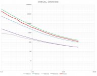
I found some time to measure a set of 3mm yellow LED´s with two different types of LDR. Attached you can find a small graph which show the output resistance versus input current curve. Have in mind that this is simply the static relationship. I do not find time to set up a dynamic measurment now.
The result is, that LED´s L-934Y from Kingbright are close to the VTL5C3 curve. The slope of VTL5C3 is 20 and the best two fitting compinations are 15 btw 25. For better fitting of the static curve it might be an idea to increase/decrease the distance of LED/LDR.
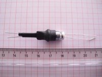
The setup is a 5mm metal LED holder used for the LDR. On top I used a 3mm plastic LED holder to mount the yellow 3mm LED in the middle of the 5mm LED holder hole. Then useing a few shrink tube to make all light-tight and mechanical fixed.
One thing about LDR absolute darknes resistance:
After less than 1 second I can´t measure any resistance. I wonder how does this happens because my Fluke 83 can measure up to 50Meg Ohm! For that I can´t calculate the dynamic range...
In the next days I will go on to measure the dynamic data.
Best Regards
Karsten
I found some time to measure a set of 3mm yellow LED´s with two different types of LDR. Attached you can find a small graph which show the output resistance versus input current curve. Have in mind that this is simply the static relationship. I do not find time to set up a dynamic measurment now.
The result is, that LED´s L-934Y from Kingbright are close to the VTL5C3 curve. The slope of VTL5C3 is 20 and the best two fitting compinations are 15 btw 25. For better fitting of the static curve it might be an idea to increase/decrease the distance of LED/LDR.
The setup is a 5mm metal LED holder used for the LDR. On top I used a 3mm plastic LED holder to mount the yellow 3mm LED in the middle of the 5mm LED holder hole. Then useing a few shrink tube to make all light-tight and mechanical fixed.
One thing about LDR absolute darknes resistance:
After less than 1 second I can´t measure any resistance. I wonder how does this happens because my Fluke 83 can measure up to 50Meg Ohm! For that I can´t calculate the dynamic range...
In the next days I will go on to measure the dynamic data.
Best Regards
Karsten
Attachments
- Status
- This old topic is closed. If you want to reopen this topic, contact a moderator using the "Report Post" button.
- Home
- Live Sound
- Instruments and Amps
- Tube Mic preamp with compressor - any ideas?