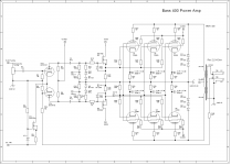
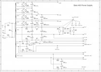
I am in the process of building a 100 watt Plexi clone, but would like to "re-engineer" it with mosfet source followers to drive the output tubes ( JJ E34LS ). I picked up 4 BUZ80A Mosfets to do the job. I am by no means an engineer, but it is my understanding that a bi-polar supply of roughly +/- 100 volts d.c.is required. The power transformer for this build has a separate two wire winding for bias voltage. It is rated for 90 v.a.c @ 50 ma. Does anyone here know if this will be sufficient voltage and current to pull this off? I found a schematic that someone posted online of a 400 watt bass amplifier. (see attachments), that uses this type of drive circuit. What changes would have to be made to the circuit shown to more or less "drop in" the BUZ80A's, and use E34ls in place of the BU50's. The power transformer I will be using will have a B+ of 460-470 volts on the output tube plates. I would really appreciate any help at all...Axerob
Attachments
Last edited:
What kind of power are you looking for? 460VDC with 6 EL34's will never get you 400W. The output transformer for this kind of power will be 'uncomfortably' large too.
As far as I see it, you've got three main options to incorporate MOSFETs in that position.
1) Use the topology as seen in your posted schematic. It uses a voltage doubler in the negative supply to get the -280V. There's another bias supply (value unknown) in front of the gate to bias the MOSFET somewhere between the +30/-280V. This will set the bias for the powertubes as well. Pretty elegant, but I've never used it. I do have some question marks about setting the bias for both the MOSFETs and powertube with the same control...
2) Provide a symmetrical supply (+/-100V for example). Keep the gate at 0V and separately bias the grids of the powertubes. This will need more coupling caps, but is more intuitive.
3) Direct couple the MOSFETs to the anodes of the phasesplitter. The anode voltage will set the bias for the gate (so no cap is required) and there's no need for another negative supply, other than the separate powertube bias. In essence, they're used the same as simple cathode followers.
Personally, I like option 3. PSU can be kept simple as the MOSFETs use the same supply as the phasesplitter and it only requires a coupling cap between MOSFET outputs and powertubes.
Most MOSFETs with the proper voltage ratings will work, since it's under a lot of serial feedback.
Thanks for your reply Funk1980. What is needed is 100 watts from 4 E34LS. I guess I didn't explain some things well enough, sorry. What is needed are 4 mosfet followers with individual bias controls.I like your options 2 or 3. Would it look something like the attached drawing? The drawing in the initial post submitted ( the bass amplifier) seems over complicated for a guitar amplifier. With a couple of tweaks, it would most likely be a fantastic Hi Fi amp. I like simple. So, what you suggest is, connect the drain to the plate supply of the phase inverter. I have read somewhere that the drain should have some series resistance, 10K comes to mind, to keep the mosfet cooler, (the mosfets will be mounted to the chassis).Is the resistor idea reasonable, or unneeded? Then what, use a bridge rectifier to generate the negative voltages needed ? That would work out to roughly -127 no load volts d.c.? Then pick off with resistors the -50volts needed for grid bias network ? Sorry for all the questions, but I am quite unsure about solid state devices. My last attempt at this (about six years past) yielded the fourth of July inside the amp chassis! So, if the drawing submitted with this reply is used, it should work, right? Again, thanks for your patience and help.
Attachments
This is a supplement to my first reply....from what I have read, in order for the circuit in my last reply to function, a negative supply voltage 2 x the bias supply (roughly -100vdc) is applied to the source resistor. The source output is then directly coupled to the grid of the E34LS. Sound right?
My bad, I see now you already mentioned the 100W  .
.
In case of option 3, you connect the gate directly to the anode (not to supply, but between resistor and plate) of each of the phasesplitters. A resistor between the anode and gate is highly recommended for stability reasons. It will not change the amount of dissipation. 1k should be enough and don't forget a protective zener between source and gate.
The drain connects directly to the B+ and the source to ground with a high value series resistor. No negative supply needed, except for the bias directly to the EL34's grids.
The option you're referring to with the split split supply can also be used, but is more complicated since an extra negative supply, like you said about twice the bias supply, is needed for the MOSFET. PSU becomes more complex and I don't see the benefits, but I could be wrong of course.
To be honest, depending on the gridleak resistors used for the powertubes (load presented to the phasesplitter), the MOSFET sourcefollowers are probably unnecessary. Unless you expect to go class AB2 or use very small grid leaks.
.In case of option 3, you connect the gate directly to the anode (not to supply, but between resistor and plate) of each of the phasesplitters. A resistor between the anode and gate is highly recommended for stability reasons. It will not change the amount of dissipation. 1k should be enough and don't forget a protective zener between source and gate.
The drain connects directly to the B+ and the source to ground with a high value series resistor. No negative supply needed, except for the bias directly to the EL34's grids.
The option you're referring to with the split split supply can also be used, but is more complicated since an extra negative supply, like you said about twice the bias supply, is needed for the MOSFET. PSU becomes more complex and I don't see the benefits, but I could be wrong of course.
To be honest, depending on the gridleak resistors used for the powertubes (load presented to the phasesplitter), the MOSFET sourcefollowers are probably unnecessary. Unless you expect to go class AB2 or use very small grid leaks.
 Relocating this to the instruments & amps forum since this appears to be guitar amplifier related. (See sub headers at top of tubes/valves and I&A forums if clarification needed.)
If you need 100W ..... 4 x EL34 tubes would suffice...
If this is for BASS, then I suggest a 4 x 6550A tube for it's headroom....
For that voltage range you have of 460V to 470V operating in Class AB1 for 4 x 6550 or EL34... Plate load of 1.7K is most optimum....
Typically what I do is float the FETs on the BIAS rail and direct couple the FET followers into the tubes.... then FETS are self biased through a divider into the source resistor..
Make sure to audio bypass the bias circuit with caps...
Hello Cerrem, What I am looking for is a way to relieve some of the blocking distortion that EL34's fall pray to. By the same token, I like to push the low end as far as I can. Would this circuit do it? (see attachment). I built a 50 watt plexi clone about five years ago that nailed the "brown sound", but also has massive low end. It becomes very flabby (blocking distortion) after the output tubes become a little worn. That's what leads me here. I am now building a 100 watt plexi with the Langer mod preamp. It will use JJ E34LS , and yes..it is a 1.7K output transformer. I am installing a 3Henry choke, but I may change it to 20 h later. I see you mention strapping a 12 volt zener across the junction of the mosfet. What wattage should I use? I want to make this as simple as possible. The attached circuit seems simple enough, but I am unsure of component values. I tried this trick some years ago, and it went up in smoke. Any help would be welcome.
Attachments

To funk1980, I believe I tried option 3 once before, and it went up in smoke. Option 2 is probably what I will go with. I'll build a bridge rectified minus supply, ( should be about -125 vdc) to float the Source. Increase the filtering 47uf/4.7k resistor/second 47uf. That should be relatively clean, then pick off, with a resistor/filter cap...the -50volts for the bias. I will be using FR107 diodes throughout the power supply...so things will be "cleaner". If you saw the last attachment I made...this would be equivalent to your solution #2...I think. I believe this circuit needs a resistor from the Drain to the positive supply rail to limit dissipation a bit. This circuit resembles an ac coupled cathode follower except for the injection of tube grid bias at the gate of the mosfet. I see you mention a diode across the mosfet for protection. Is this the 12 zener diode I have seen mentioned in the Ampage posts? If it needs to be a zener, what wattage should be used?
With that high B+ some Current production probably won't last long...I had JJ E34Ls Drift badly/ arc/ smoke them selves at only 420v on plates/screens....Finally ended up getting some good ones that don't go to hell within a month or 2..... and you are going to be smoking them a lot higher with voltages....I would go with NOS if dead set on EL34s old Tesla's are worlds better anyways or RFTs etc...Winged Cs were not my thing really, too Edgy/Sharp/Presence...What couplings you going to use?
Last edited:
The zener is just there to protect the MOSFET in case the gate would exceed the maximum Vga. A 0.5W is fine. Some MOSFETs have one build in already, but it's good practice to always include one.
I suggest looking into the UF4007 diodes and the like. Reverse recovery time is about 7 time faster compared to the FR107.
I suggest looking into the UF4007 diodes and the like. Reverse recovery time is about 7 time faster compared to the FR107.
The zener is just there to protect the MOSFET in case the gate would exceed the maximum Vga. A 0.5W is fine. Some MOSFETs have one build in already, but it's good practice to always include one.
I suggest looking into the UF4007 diodes and the like. Reverse recovery time is about 7 time faster compared to the FR107.
Definitely I will vouch for the Ultra Fasts...I can hear a difference.
Hello Cerrem, What I am looking for is a way to relieve some of the blocking distortion that EL34's fall pray to. By the same token, I like to push the low end as far as I can. Would this circuit do it? (see attachment). I built a 50 watt plexi clone about five years ago that nailed the "brown sound", but also has massive low end. It becomes very flabby (blocking distortion) after the output tubes become a little worn. That's what leads me here. I am now building a 100 watt plexi with the Langer mod preamp. It will use JJ E34LS , and yes..it is a 1.7K output transformer. I am installing a 3Henry choke, but I may change it to 20 h later. I see you mention strapping a 12 volt zener across the junction of the mosfet. What wattage should I use? I want to make this as simple as possible. The attached circuit seems simple enough, but I am unsure of component values. I tried this trick some years ago, and it went up in smoke. Any help would be welcome.
I use just one bias feed divider.... I float the FETS on the bias voltage divider.. The have the FETS self bias, so the FETS move up and down with the bias voltage so not to disturb their operating point... this direct coupled to the output tube grids.... With bass amps with very punchy a snappy speakers, you will get standing waves coming back up the transformer that can SUM with existing in phase signal and then exceed breakdown voltage....tubes will arc over unless you protect them....
I've used MOFET Source followers to drive output tubes in a HiFi Amp.
See Post #602 here for schematic:
http://www.diyaudio.com/forums/tubes-valves/72536-el84-amp-baby-huey-61.html
This design shows current source loads for the source followers which can be replaced by a simple resistor.
The rules of thumb are:
The -ve supply needs to be approx 3 times the typical bias voltage
The source follower load resistor + the grids stop resistor needs to be less than the max Rg1 value for the tube in fixed bias. This will determine the source follower current too.
The MOSFET Drain voltage needs to be high enough such that on max positive signal swing at the source (it will swing to 0V or maybe a volt or 2 above 0) you need to have say 25V left across the MOSFET (Vds). This minimises capacitance modulation with signal. That would suggest a +30V rail (minimum) for the MOSFET drain.
You can obviously use higher voltage than that on the drain but all it does is add to the device power dissipation.
The +30V (or whatever) rail needs to be well bypassed. Add a film cap across any electrolytic you use on the rail.
Hope this of some help.
Cheers,
Ian
- Status
- This old topic is closed. If you want to reopen this topic, contact a moderator using the "Report Post" button.
- Home
- Live Sound
- Instruments and Amps
- Advice needed on 100 watt Plexi clone build