I got this 18 watt combo that I am obviously having a hard time understanding. It is my buddies and he dropped it off and asked me to look at it because it doesn't sound right lately. First things is that it doesn't put out rated output power, so I figured I would go through it with a fine tooth comb for him because this is his favorite amp. He only uses the tremolo channel so I started there, I am measuring a gain of 34 for the first voltage gain stage The amp is wired correctly according to the schematic, the Vpp is 300 and the Va is 110. I replaced the bypass capacitor with a new one and it still has low gain
I calculated that the gain should be around 77 for this circuit, is that correct?
100 * 220000 / (220000+62500) = 77
I am using 220k for the load, which would be the volume pot in parallel with the 470k resistor to ground......maybe this is my error?
-bird
The amp is wired correctly according to the schematic, the Vpp is 300 and the Va is 110. I replaced the bypass capacitor with a new one and it still has low gainI calculated that the gain should be around 77 for this circuit, is that correct?
100 * 220000 / (220000+62500) = 77
I am using 220k for the load, which would be the volume pot in parallel with the 470k resistor to ground......maybe this is my error?
-bird
Attachments
Last edited:
Swap V2 and V3 - any change?
Good idea, and I was thinking it was a weak tube issue but I tested the tubes in my Hickok 539b and they tested good. I haven't had the time to look at it again but when I do I will probably try all known good valves from my stash just to be sure.
sorry if this is alittle off topic after looking at the linked schematic can you clear me up on how the HI & LO tremelo input jacks provide a gain difference to the input of V3a?
By loading the high output impedance of the guitars passive pickups, "Hi" has a 1 Meg grid leak resistor and the "lo" uses the "Hi" channels 68k grid stop resistor as it's grid leak resistor. The gain in the channel doesn't change but the gain of the passive pickups does.
Test V2 or swap V1 and V2 and measure both outputs from PI. If still unbalanced and distorted try removing EL84s and see if problem goes away, other try swap EL84 and see if problem moves from side to side...
I tried all fresh tubes from my stash that are definitely good and the problem is with the same section of the PI.
leaky coupling cap perhaps?
I don't have any DC present at G1 of the power tube that has the bad signal but I am still thinking it's that coupling cap too. I will replace it and see what happens.
It's not the caps so back to square one. One at a time I did both blocking caps feeding the power tubes, and the .022u and .01u feeding the LTP. I did notice that when I plug the signal into the normal channel (which feeds the other side of the LTP) the opposite side of the waveform is distorted in the output. So depending on what side of the LTP gets the signal determines which side of the sine wave gets distorted on the output.
Thanks guys, I believe you both are basically telling me to do the same thing, which is what I plan to do next. I am also planning on lifting the coupling caps going to the grids of the power tubes before the grid leak resistor and check with my scope, this will load the PI differently because the input impedance of the scope is 10k......where I was getting 6V rms I should only get 1V rms.
The quiescent DC voltages/currents around the PI looked fine from what I remember except for a lower than expected reading at the grids........I account the difference is caused by the loading of the digital multimeter, but plate voltages were good and bias voltage was good. I did notice that the "tail" of the PI is larger than normal, instead of the 47k value in the schematic this one is outfitted with a 56k.
Thanks for the tips I will do some probing and check back.
leaky coupling cap perhaps?
+1
If the phase splitter is equal resistors type then the AC volume should be the same on each resistor.
Its usually capacitors causing problems especially if the amp is of any age.
Coupling caps C16 and C17 have been changed to brand new Mallory 150's, the white ones 630V rated 5%.
I lifted C1 on the volume pot side and grounded it while driving the tremolo channel and no help. I also lifted C18 on the volume pot side and grounded it while driving the normal channel and no help.
I am expecting to get at least 12V clean out of this amp into 8 ohm load before it starts to clip.
With a 20mV 1kHz sine wave input and the volume about 3/4 (250mV feeding the PI) I should and do get 6V going to the grids of the power tubes and this should give me max output power (I think) BUT I am only getting around 7V out to the dummy load and this is when it starts to clip (only on one side of the sine wave).
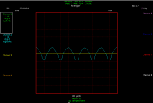
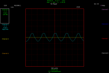
I took some screen shots of the clipping. One is of the normal channel showing one side of the sine wave clipping on the output, and the other is the tremolo channel showing clipping on opposite side of sine wave.
Both screenshots are taken with the volume maxed out. Signal voltages taken at power tubes control grid and speaker output.
Normal channel G1 left tube 11.6V and G1 right tube 12.35V output at resistive load 10V
Tremolo channel G1 left tube 10V and G1 right tube 9.5V output at resistive load 9.5V
I lifted C1 on the volume pot side and grounded it while driving the tremolo channel and no help. I also lifted C18 on the volume pot side and grounded it while driving the normal channel and no help.
I am expecting to get at least 12V clean out of this amp into 8 ohm load before it starts to clip.
With a 20mV 1kHz sine wave input and the volume about 3/4 (250mV feeding the PI) I should and do get 6V going to the grids of the power tubes and this should give me max output power (I think) BUT I am only getting around 7V out to the dummy load and this is when it starts to clip (only on one side of the sine wave).
I took some screen shots of the clipping. One is of the normal channel showing one side of the sine wave clipping on the output, and the other is the tremolo channel showing clipping on opposite side of sine wave.
Both screenshots are taken with the volume maxed out. Signal voltages taken at power tubes control grid and speaker output.
Normal channel G1 left tube 11.6V and G1 right tube 12.35V output at resistive load 10V
Tremolo channel G1 left tube 10V and G1 right tube 9.5V output at resistive load 9.5V
Attachments
I am starting to think this is a output transformer problem, it's a Mercury Magnetics and pretty sure it costs an arm and a leg but at this point I don't see it being anything else.
You can test it by removing it and applying AC voltages to primaries and monitoring the secondaries. You should see reduction in secondary voltage scaled to primary : secondary ratios.
- Status
- This old topic is closed. If you want to reopen this topic, contact a moderator using the "Report Post" button.
- Home
- Live Sound
- Instruments and Amps
- Marshall 1974X