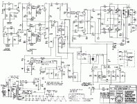
I am rebuilding a Traynor YCL-3 Amp. It has 4 Jugs of type 6CA7. I noticed one thing right away - there are two resistors (R21 and R22) that appear to be screen resistors. They are marked as 47 Ohm and both have doubled in value over the years. 4 jugs - but only TWO 2 screen resistors. The other two screens are tied together and go directly to the bias supply.
V8 and V10 have the 47 Ohm screen resistors - V7 and V9 do NOT have the resistors in the screen circuit....
Seems to me that it would create an unbalanced situation if in face the screen resistor is used for the classic functions (Secondary emission provention etc...)
I could not get my scanner to capture the schematic that shows this but a quick google for YCL-3 Schematic will bring it right up.
I really appreciate any assistance on explaining why this final circuit is setup this way.
Thanks in advance
John
N6API
Peter Traynor used the minimum of screen and control grid resistance possible. The screen and control grid resistors are by tube position, so that's a unmodified amp you have. The stoppers are on the "outside" pair of tubes, because they'd oscillate without them. The "inside" pair of tubes don't have them.
A common mod to this amp is to change to 4 x 1k 5 watt screen resistors and 4 x 1.5k control grid resistors.
A common mod to this amp is to change to 4 x 1k 5 watt screen resistors and 4 x 1.5k control grid resistors.
Last edited:
- Status
- This old topic is closed. If you want to reopen this topic, contact a moderator using the "Report Post" button.
