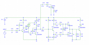
Hi I just came up with a new optical compressor pedal design using all discrete transistors, I haven't built it just yet and I was hoping to get some feedback before I do. so without further ado here is my schematic:

The first stage is a two transistor shunt feedback amplifier with a photo-resistor in the feedback path so that as its resistance decreases I get more negative feedback and therefore less output. the second part consists of a buffer followed by an envelope detector and then a fourth transistor to drive the LED.
Anyone have any suggestions on how to improve this circuit before I go ahead and build this thing?
Build a tried and true circuit which is guaranteed to work, this one will not.
The kind of conceptual errors it has hints that you are not yet up to snuff to desigh such a circuit.
1) the biasing will jump up and down all over the place, the LDR not only affects audio signal (what´s expected) but the bias point of the complementary pair.
2) the third transistor has unity gain, unamplified signal passing through it will not be high enough to turn diode rectifiers on, except at levels so high that you´ll be reaching clipping levels, so no headroom.
3) the bridge rectifier won´t work the way it´s connected.
4) the right top diode does nothing.
5) the right bottom diode is shorted.
Sorry.
Thanks for pointing out the problems with my design, I will now take some time to correct them. As for tried and true designs, I would build one but none of them seem to use discrete transistors like I want to, It would be fairly trivial to design one using op amps but then I would learn nothing. Designing this is a learning experience and I know I could just go ahead and build someone else's design but I still prefer to do it myself.
also the right bottom diode is not shorted, as is shown in the schematic the cathode is grounded but the anode is not.
also the right bottom diode is not shorted, as is shown in the schematic the cathode is grounded but the anode is not.
Last edited:
So the fourth transistor is not referred to ground?also the right bottom diode is not shorted, as is shown in the schematic the cathode is grounded but the anode is not.
Where will the Led current come from?
Ok, back to the project:
If you want to practice and design everything from scratch, fine with me
")
You´ll need:
1) a gain stage with negative feedback, across which you can slam your LDR .
AC coupled, or you will repeat the problem.
or:
a fixed gain stage, and some R/LDR attenuator
2) a good audio rectifier
3) some controllable time constant, usually some R-C-R network which allows attack and delay be set at will.
You can simplify that by trusting typical LDR response times ; it does work, but is not adjustable.
Your choice.
4) some means to supply current to the LED proportional to the detected audio voltage
After you have those building blocks , you combine them together and tweak for desired results.
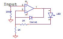
So I redid the design but this time a bit more legibly. The first stage is a feedback amp again but with a different topology which can more easily be controlled by a photo-resistor, the output of this sent to a phase splitter and then rectified, filtered and sent to a fourth transistor to drive the LED. I did some SPICE testing on this design and it seems to work as far as I can test it but the real world is always different. I decided to simply rely on the photocell for attack/release simply because this is intended to be a guitar pedal and I want to keep it reasonably simple, if this works out I may design a studio quality compressor with more thorough controls.
EDIT: The level pot should read 100k not 10k
EDIT: The level pot should read 100k not 10k
Attachments

Are you challenging yourself to do it differently? There are voltage gain control designs that are simpler instead of using optical design.
Even if you insist on doing optical design, your rectifier circuit in both are highly questionable. You are doing open loop and I don't see how you can get rid of the dead spot. Even the second circuit, I don't see how your THRESH POT can adjust out the dead spot. The circuit is AC coupled by C1 and C4. There is no voltage across the THRESH POT. You still have to swing 0.7V before D1 OR D2 can turn on.
You need to use an opamp with high forward gain, then put the LED in the feedback loop. Use the LED as rectifier to create the envelop follower. The high open loop gain of the opamp can take up the dead spot much better. If you insist in using discrete transistors, then you have to create an amp with high gain and put the LED in the NFB. Look at envelop follower circuits, it's very basic and have many examples.
There are so many sustainers around, study a few before you do this.
Last edited:
Why do you want to build a discrete circuit? I get the impression a lot of pedal builders prefer to use discrete transistors because it tends to lead to minimalist circuits with a bare minimum of parts. But in this case you're using MORE parts to create a compressor with LESS perfomance than a more conventional design... why?
Even if you insist on doing optical design, your rectifier circuit in both are highly questionable. You are doing open loop and I don't see how you can get rid of the dead spot. Even the second circuit, I don't see how your THRESH POT can adjust out the dead spot. The circuit is AC coupled by C1 and C4. There is no voltage across the THRESH POT. You still have to swing 0.7V before D1 OR D2 can turn on.
There is actually voltage across the Thresh pot, it works as a balanced attenuator. The led/diodes wont turn on until a certain threshold and that is all part of my design, the compression wont occur until the signal reaches that threshold and the thresh pot will attenuate the signal so that it hits the threshold earlier or later depending on the users preference.
I was interested in building a simple discrete compressor and I had a different idea I put up on this thread. http://www.diyaudio.com/forums/inst...-preamp-boost-eq-eq-boost-4.html#post5212163I
It seemed to work, the led comes on and the volume goes down, but I haven't done any kind of advanced testing. I used a transistor as a switch on a resistor to change the gain of a signal. Seems like there are a paucity of simple compressor schematics out there, and the simple ones use vactrols usually. Thanks for the thread its very nice to see how different people approach solving different problems.
It seemed to work, the led comes on and the volume goes down, but I haven't done any kind of advanced testing. I used a transistor as a switch on a resistor to change the gain of a signal. Seems like there are a paucity of simple compressor schematics out there, and the simple ones use vactrols usually. Thanks for the thread its very nice to see how different people approach solving different problems.
- Status
- This old topic is closed. If you want to reopen this topic, contact a moderator using the "Report Post" button.
- Home
- Live Sound
- Instruments and Amps
- Discrete Compressor pedal design