So, nobody knows how to decrease the signal at opamp output, before the output cap?
Why before the cap? Just use the volume control.
470k in series with the input would give a gain of 1/2.
I don't have it in the breadboard anymore but I tried other values and it sucked the highs. A lot.
Wouldn't you decrease the value of the 1m feedback resistor to get less gain?
Perhaps that may be better but it could affect the tone control response.
It did affected the eq, enormously, too much for a compromise.
Why before the cap? Just use the volume control.
Because I need it at that point, where the second circuit works. That one doesn't work with a decouple (?) capacitor before it.
Anyway it was for today and I already changed the circuit for an inverting one (is it?) with a variable "sensitivity", that is changing the feedback resistor (I guess), the famous Guitar control from redcircuits. No problems with that one alone, only the several inconveniences, the many many reasons why I choosed the other over this one initially.
But I do have a question: I want to simplify the ciruit and this guitar control uses a voltage divider of different values than another circuit that will be also included in the box. I wanted to use one for all 3 (or 5 should I say?) opamps: one TL071, one TL072, and one NE5532. I read that it's important to respect the values, but no idea how critical is it nor if that "important" refers to a ratio or each component separately I don't want hum aplified all over this circuit that aims to good quality. One uses 2x 22k and a 100uF and the other uses 2x 10k and 47uF (NE5532). Neither I know if when all under load will it be too much for one divider alone to feed them or is it better anyway to use 2 different dividers because of their different respective values. (I found this but don't have time to read it and the knowledge background to undertand it appropriately, and this that doesn't say it's too critical ).
So that's the question, what do I do?
Why before the cap? Just use the volume control.
Attenuation here just reduces the headroom, making it more susceptible to overload didtortion.
I made the booster described in thiss thread, original link here:
Clean boost for guitar (or bass) | jer00n.nl
I want to know if its safe to plug the output to a mic input in the computer soundcard. My notebook does not have line in. Just a combo trrs plug.
Are there any impedance or voltage issues since its output line signal?
I dont want to damage the mic input. Its an expensive notebook.
I thought of replacing the pot with a fixed resistor, just add a series one for safety of dont increase the volume too much!
I measured the output impedance of this circuit, its close to 5k (don´t know if I measured the right way though! I just set the multimeter to ohms.
Thanks!
Don´t think you will blow the mic input but you can easily overload it.
When you have just a single input, it´s common for the notebook to set said input gain to different levels, choose the lowest gain setting and of course uncheck any "gain boost" option.
That way, Mic input behaves as a passable Line input.
Output impedance varies between zero and 2500 ohms, depending on pot setting.
In my opinion, using a series resistor is a good idea. The opamp can put out up to maybe 6 volts peak-to-peak, worst case, while the mic input is probably expecting 0.1 volt or so. A series resistor would limit current flow if the signal is too high, and it's usually excessive current flow that damages those delicate semiconductors (input stages in your sound card).I thought of replacing the pot with a fixed resistor, just add a series one for safety of don't increase the volume too much!
You might also try putting a wire jumper (short) right across the 220k feedback resistor. That will cut down the opamps gain to unity, so the output signal will be no bigger than the guitar signal (but will still be buffered). My guess is that this will still be plenty of signal for a microphone input. And if I'm wrong, it's quite easy to remove that jumper, and go back to a voltage gain of 3.2 times.
If you are very concerned, you can also put a pair of parallel, back-to-back red LEDs across the output signal. They will do nothing as long as the signal stays under about 1.5 volts peak, but if the voltage exceeds that, the LEDS will conduct and clip the voltage. In other words, they will prevent excessive voltage from being fed into your expensive notebook.
I'm extremely leery of connecting external electronics to expensive tablets, phones, notebooks, and desktop PCs. You are quite right, it is entirely possible to damage these expensive devices if something goes wrong. The probability is low, but consequences are severe if that improbable event does occur, so overall risk is high. (Like being in a car accident - low probability, but severe consequences.)
Incidentally, I just read through this entire thread, and it was quite a painful read. The thread got off to a good start, immediately went sideways, and was brought back on track with excellent advice from Voltwide and J.M. Fahey and a couple of other people. Unfortunately, that did not last, and the entire thread immediately went to *@%&@$, just pages and pages of utter nonsense, mixed in with total garbage, poor advice, and complete confusion.

The whole thing is quite tragic, especially because a couple of newcomers to the hobby were left with only bad advice to follow. That really bothers me.
-Gnobuddy
Excellent! Gnobuddy! You were right! It was outputing 2vac on peaks.
I added first two parallel red leds from positive to ground on output, legs inverted like the figure then It measured 1.8vac Both of the light up bright!
So I exchanged for 2 zener glass diodes I had, although I did not manage to read the markings, it gave 0.5vac
Limiters & clipers
This page is much worth reading, about the limiters you mentioned.
I added a 500ohm resistor in series, my pot is 5k also, but even if you have a 10k pot, when it is all open, it yelds next to 0 Ohm. With this resistor we have always 500ohm, plus the pot limiting.
The result is multimeter reading from 5-10k on the output, with 0,25 vac when guitar strumming. With full volume on the pot.
I had to change the 220k resistor from ic pins 2-6 to 390 k to achieve a reasonable gain level on the mic input, The 100k resistor remained because decreasing it generates a lot of humming.
You can actually enter the formula: 20*log(1+(220/100)) on Google to calculate the gain. The original circuit results 10.10.
My modification 20*log(1+(390/100)) results in 13.80
According to the original project:
Clean boost for guitar (or bass) | jer00n.nl
"The maximum gain of this circuit is about 10 dB. If you need more (which I doubt), increase R2 (or decrease R1). The gain A = 20*log(1+(R2/R1))"
The On/Off popping sound was eliminated using a on/off switch potentiometer, you have the turn the volume down to switch off the circuit, this pot has a switch inside to break the 9v power. I don´t even have the 1M pulldown-resistor. It makes no popping sound at all.
I discovered that the mic port has a 2.7v bias, to power an electret mic.
I decided to stop messing with this mic port because there are several complains about this damaged plug on lenovo website. Maybe its better to buy an external sound card!
I have bought a cheap guitar link but did not satisfy me. very poor quality indeed.
Thanks!
I am using Lenovo X220 and an EMU0202 or EMU tracker USB-soundcards for audio measurements. Both provide an high-impedance line in 6.3mm jack input suitable to directly plug in an electric guitar.
Certainly you may insert any sound processing pre-amp, distortion or whatsoever.
I bought these soundcards used for little money on ebay.
Noise and THD performance (24bit) are excellent!
Certainly you may insert any sound processing pre-amp, distortion or whatsoever.
I bought these soundcards used for little money on ebay.
Noise and THD performance (24bit) are excellent!
That formula is correct, if you want the gain in decibels. That's what the 20*log() part does - convert to decibels.You can actually enter the formula: 20*log(1+(220/100)) on Google to calculate the gain. The original circuit results 10.10.
Another way to express gain is simply a ratio (how many times bigger is the output than the input?). This is given by {1+220/100}, and works out to 3.2 times, which is the number I quoted earlier. Note that the 20*log() bit is not part of this formula.
To (hopefully) make it all clear, a gain of 3.2 times is exactly the same thing as a gain of 10.1 dB. They are just different ways to describe the same gain. Each of them has some advantages, and some disadvantages.
Beware of increasing the gain of the op-amp stage too much, otherwise it will run out of headroom, and start to clip on peaks of the guitar signal. That sort of op-amp clipping usually sounds extremely nasty.
That sounds like a wise move, there are lots of affordable external USB sound cards these days. The cheap ones probably still require a buffer for guitar, but if something goes wrong, you're much less likely to fry something inside your notebook computer.Maybe its better to buy an external sound card!
I've found a couple of USB microphones for a couple of bucks each at local thrift stores. These come from some sort of Guitar Hero or Rock Band or karaoke toys. They work quite adequately for quickly capturing guitar or vocal ideas on my PC. Cheap as they are, guitar is such a crude-sounding instrument that I don't hear any limitations coming from the mic. (I don't push SPL limits, I'm sure these mics would clip if the sound is too loud.)
It might be an interesting project to open one up and see if a guitar signal can be interfaced where the microphone capsule normally connects.
-Gnobuddy
Ok, I sorted it out using a cheap guitar link usb device, the trick was that plugging the guitar directly to it, you had to set the software volume to max. And using the preamp, you can set it to 50% without the software gain setting with clean sound.
Im trying to add some fuzz/overdrive to it, adding inverted diodes between pins 2 and 6 of tl071 but with no avail. The sound does not change at all. Does anyone knows how to add distortion to this circuit and possibly a pot to control it?
Best Regards
Celso

Im trying to add some fuzz/overdrive to it, adding inverted diodes between pins 2 and 6 of tl071 but with no avail. The sound does not change at all. Does anyone knows how to add distortion to this circuit and possibly a pot to control it?
Best Regards
Celso
With a gain set to 10db and presumable not very much guitar pickup level (maybe single coils pickups?) you can not expect significant distortion with this setup.
Try to increase gain to something like 30~50dB, and you will get distortion with clipping diodes as mentioned above.
Try to increase gain to something like 30~50dB, and you will get distortion with clipping diodes as mentioned above.
Hello, I will be very happy to get your help
I am looking for a buffer-pre-amp circuit for an Acoustic guitar Piezo pickup, a raw one, probably above 10M impedance...
I ao considering using the following circuit ::::

I can see that most of you are happy with this design,
So I wonder if that will be ok for Piezo too and not magnetic pickup..
another question is - what is the output impedance for this circuit? I am trying to design a tiny "sound card" so I want the guitar to be connected to PC through this preamp- then PCM1803A with 40K input impedance.. and then the I2S with USBStreamer...
Thanks a lot
I am looking for a buffer-pre-amp circuit for an Acoustic guitar Piezo pickup, a raw one, probably above 10M impedance...
I ao considering using the following circuit ::::
I can see that most of you are happy with this design,
So I wonder if that will be ok for Piezo too and not magnetic pickup..
another question is - what is the output impedance for this circuit? I am trying to design a tiny "sound card" so I want the guitar to be connected to PC through this preamp- then PCM1803A with 40K input impedance.. and then the I2S with USBStreamer...
Thanks a lot
<answer class=standard>Im trying to add some fuzz/overdrive to it, adding inverted diodes between pins 2 and 6 of tl071 but with no avail. The sound does not change at all. Does anyone knows how to add distortion to this circuit and possibly a pot to control it?
Read through
a) the show your creative clipping circuits thread.
b) an analysis of the big muff and tube screamer circuits and how they are used for different things
And
c) have a wander through the circuits and sound clips at runoffgroove such as the Supreaux Deux, Peppermill and Thunderbird
</answer>
In short, you need to know what you're after. Then we can talk circuits and why your 10db booster will never give you fuzz
Frankly, I'd be getting an overdrive pedal (a cleanish one like the Boss OD-2 or BD-2 or .... ) and one or two EQ pedals (wired up EQ-OD-EQ) and work out what you need long before I messed with your guitar-to-line preamp
Last edited:
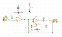
Is your piezo pickup the type that looks like a thin long strip, which fits under the saddle? If so, it will typically have a capacitance of maybe 500 pF - 1 nF. If you build the traditional audio piezo preamp, you will indeed need about a 5 mega ohm input resistance....Piezo pickup, a raw one, probably above 10M impedance...
However, this is quite a bad idea, especially if the preamp is located more than a few inches from the piezo itself. With such a high input impedance, the circuit will be extremely prone to pick up hum. Simply moving your right hand into playing position near the bridge of the guitar may be enough to cause a loud hum from your speaker.
So I designed a very different type of piezo preamp for you. Rather than try to have an enormously high input impedance, this one has the opposite, an extremely low input impedance, which makes the circuit much less likely to hum and buzz. The current from the piezo pickup is fed into an integrator built around U1A and C1. What comes out of this integrator is exactly what you want - a nice low-impedance signal, with a flat frequency response down to below the lowest note from an acoustic guitar in standard tuning (about 83 Hz.)
A second op-amp (there are two opamps in the suggested TL072) is used to amplify the signal from the piezo, and it's gain can be adjusted with the 100k gain pot. I don't know how much signal your piezo puts out, so I don't know how much gain you need. But the pot has a wide gain adjustment range, so it should cover what you need.
I've designed this to be powered by two 9V batteries, wired in series to provide +9V, 0V, and -9V. You can make slight modifications that will let you run the circuit on a single 9V battery, but that will reduce headroom.
Output impedance of an op-amp circuit is extremely low, a few ohms or even less. However an op-amp can become unstable if you connect it to a long shielded cable (too much capacitance), so I've added the 1k resistor R5 to my circuit to keep the op-amp happy.what is the output impedance for this circuit?
-Gnobuddy
Attachments
- Status
- This old topic is closed. If you want to reopen this topic, contact a moderator using the "Report Post" button.
- Home
- Live Sound
- Instruments and Amps
- Guitar Level to Line Level Hi-Quality Preamp