I've been trying to understand how a tube data sheet plate characteristic graph works, generating the "load line", etc. Question: A two stage preamp (12AX7 for ex) doesn't need the same headroom (voltage swing without clipping) on the first stage (due to a much smaller input signal), but I commonly see both having the same size load resistor (say 100K), and both off the same B+. How would I lower the B+ to the first stage, to reduce it's gain? Wouldn't just an added dropping resistor be considered part of the "load resistor", thus increasing the gain? Would putting a filter cap after this additional resistor "decouple" it from the equation? My goal is to then avail more voltage to the second stage, and more headroom for it's larger input signal. Thanks!
If you want to reduce the gain of the first stage and assuming that both stages are ordinary self-biased common-cathode stages, you can either reduce the plate resistor, or decide not to decouple (a part of) the cathode resistor, or reduce the bias current and thereby reduce the transconductance. You can reduce the bias current by increasing the cathode resistor or as you suggest yourself: by reducing the supply voltage, for example with an RC filter. Theoretically, the transconductance varies with the third power root of the current, so you need to reduce the current a lot to get a noticeable transconductance reduction.
Are there any other requirements, such as noise levels?
Are there any other requirements, such as noise levels?
According above, You will change the quality of sounding, because in every work point the sound is little bit different, IMO.If you want to reduce the gain of the first stage and assuming that both stages are ordinary self-biased common-cathode stages, you can either reduce the plate resistor, or decide not to decouple (a part of) the cathode resistor, or reduce the bias current and thereby reduce the transconductance. You can reduce the bias current by increasing the cathode resistor or as you suggest yourself: by reducing the supply voltage, for example with an RC filter. Theoretically, the transconductance varies with the third power root of the current, so you need to reduce the current a lot to get a noticeable transconductance reduction.
Are there any other requirements, such as noise levels?
I wrote somewhere in the forum for decreasing of gain.....if parallel to cathode res. is shunt cap in uF /it's enough for one triode/, You can connect to the cap in series trimmer potentiometer /middle it point short to one end of potentiometer/ with nominal about the same like cathode resistor and You can adjust the gain from min. to max.
But the choice is Yours....
I've been trying to understand how a tube data sheet plate characteristic graph works, generating the "load line", etc. Question: A two stage preamp (12AX7 for ex) doesn't need the same headroom (voltage swing without clipping) on the first stage (due to a much smaller input signal), but I commonly see both having the same size load resistor (say 100K), and both off the same B+.
For hollow state work, plate loads are chosen for best distortion performance, not gain or headroom. It's especially bad to reduce the plate load on a triode since distortion performance improves with lighter loading. Remember: the 12AX7 has a very high rp= 90K and won't tolerate very well a plate load much smaller than 100K, and more would be better.
How would I lower the B+ to the first stage, to reduce it's gain? Wouldn't just an added dropping resistor be considered part of the "load resistor", thus increasing the gain?
For DC loadline purposes, it would indeed be part of the plate load. For AC, you could decouple the extra resistance with a bypass capacitor, and then the AC loadline wouldn't include this extra resistance. You could also reduce the voltage with a voltage divider or active regulator/active decoupler. If it's excessive gain you need to lose, it's better to tap off the plate load instead of decreasing it (more distortion) or including NFB to reduce the closed loop gain.
Would putting a filter cap after this additional resistor "decouple" it from the equation? My goal is to then avail more voltage to the second stage, and more headroom for it's larger input signal. Thanks!
Why bother with any of this in the first place? If you have adequate headroom in the output stage, then there really is no such thing as excessive headroom in the lower level stages. For distortion purposes, it's always best to have the output stage clip before any previous gain stage. If two or more stages clip at the same time, that makes for some truly ugly distortion, especially if there's NFB involved.

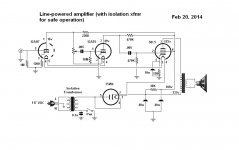
I moved my posting to the Inst & Amps forum, including the attached schematic to assure all I am playing safely.....(thanks Mooly). Adding the 12AU7 stage to the original intercom amp (a Masco ST-1) gave me more gain than I wanted (even with only 19 volts on the plate!). As you can see, I don't have much B+ to play with, but turns out boosting it (running both preamp tubes from the 50C5 plate not screen) made for terrible farting. Am digging into tube data plate graphs, but drawing a load line from 127 plate volts to 0.6 mA is barely on it!. Still, my goal is to predict, from a given tube mu, known input signal and B+ available: what my output voltage swing will be, if any of it will be limited (clipped), and what to change to produce/minimize grid clipping and/or plate clipping. Was directed to a "split-load" paper by Steve Ahola, is VERY informative. One tool I can use. I want to "ration" available line voltage to optimize its use/need. I have Magantz's book and the P1-eX (AX84) dissertation. Lots to digest!
Attachments
Having the power switch on the ground side of the secondary is not very safe.
I was given a cheap Chinese record player that was set up the same way: switched in the secondary of the PTX. You had to unplug in order to fully power down.

The low plate voltages of this circuit is exasperating me! A B+ of 108VDC and plate current of 108/470K= 0.11 mA is barely even on the plate graph for a 12AT6.... How does this tube even work?? Has anyone written anything about this realm of tube application?
See the other thread, you need to change the B+ voltage drop resistor to a much smaller value (plus a bypass capacitor say 20uF) , and add a plate resistor.
The 12AT6 was in the intercom originally.....I'd hook you up with the original designer, but he's probably dead (RIP)....I added a 12AU7 (low mu), but have a 12BH7A, with a Mu of 16.5... may try it instead. Don't have many other 7pin tubes (other than a matched pair of 6V6 clone 6AQ5A's that I'm dying to push-pull for 10 watts, but that's a future project!).
- Status
- This old topic is closed. If you want to reopen this topic, contact a moderator using the "Report Post" button.
- Home
- Live Sound
- Instruments and Amps
- A technical triode preamp question