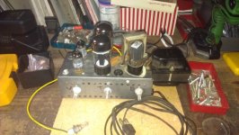
Well after finishing turning an old Webcore phono amp into a nice-sounding Princeton-ish clone, running 6Y6s with a 5Y3 (16W) or 6V6s with a diode full-wave rectifier (20W), I now have a little 12AU6/50C5/35W4 intercom to play with. It peaks out at 3.4W on the 50C5 plate, but want more gain.... will remove the xfmr that let the speaker work as a mic, and add a 12AU7 for a 2nd gain stage and tremelo. Using the Gregory Mark V as a guide. And add a 3-prong AC cord to keep the line AC off the chassis!
Attachments
What a difference a gain stage makes!
Added 1/2 a 12AU7 to my "intercom", and am now using all the headroom this little guy has to offer. Powered the heater from a Variac, but will add the tube to the heater "string", which will allow me to remove a fat 300R dropping resistor. Breaks up now above 7 on volume. Makes an amazing amount of sound thru a 12" cab I have hooked up to it! Amp rolls off high freqs too much, need to look for the cap causing it and change its value. Then add a 9-pin socket where the mic xfmr used to be, and start working on the tremelo....
Added 1/2 a 12AU7 to my "intercom", and am now using all the headroom this little guy has to offer. Powered the heater from a Variac, but will add the tube to the heater "string", which will allow me to remove a fat 300R dropping resistor. Breaks up now above 7 on volume. Makes an amazing amount of sound thru a 12" cab I have hooked up to it! Amp rolls off high freqs too much, need to look for the cap causing it and change its value. Then add a 9-pin socket where the mic xfmr used to be, and start working on the tremelo....
Attachments
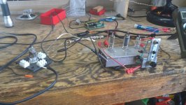
I love how your test beds use the longest wires you can possibly find. haha... ")
Cool project, nice work. Gives me ideas to look for other old equipment to cannibalise instead of looking for broken guitar amps.
Could your treble roll-off be caused by Miller Effect? I can't really see from the schematic you posted, but you already know about playing with grid stopper values to adjust roll-off from your "Champrinceton" project.
Last edited:
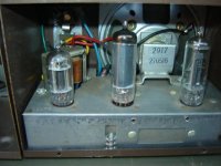
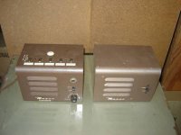
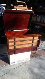
There is a method to my madness....long unshielded leads make for easy hookup, and if it hums or oscillates I know where to start looking. I found a 0.02uF cap across the OT primary, was killing the treble! Ready to mount a 9-pin socket and wire it up! Bought it for $40 (too much), but got that killer little P-P 6V6 phono for free at a garage sale where I was picking up a Raven RG-20 for $15. Just started talking tube to the guy, and the next thing I knew he was giving it to me! All evens out, all good. Hate to toss the cabinet, thinking of something to do with it....
Attachments
Last edited:
Same tube compliment in my 1959 Silvertone 1451. I use a Boss EQ pedal set for flat boost to increase overdrive potential when wanted. I measured the actual gain from the 12au6 and it's 100 ! I didn't believe it until I checked the specs for the 12/6au6 and saw the potential. It's just enough to overdrive the 50c4 a little with loud pickups. New 6" Weber speaker sounds good.
Thank you for your concern! I do want to stay "above ground". Have a question.... How does an isolation xfmr prevent the risk of electrocution? It only takes 15 mA going through your arms to stop your heart.... Where I work, we lift live 110AC all the time, tape off the leads with our bare fingers, and exercize "control" over the hazard with our technique. We have to work on most equipment "hot", and assume it is hot even when told it is "de-energized". On an amp, even with a PT you can have up to 400VDC when you hook your meter across a plate resistor. I do have a 3-prong AC cord, and my bench power is wired correctly. Another question - does a Variac afford the same protection as an iso xfmr? Thanks again!
It doesn't prevent the risk of electrocution it just reduces the likehood considerably.
With the isolation tranny the circuit is isolated from active and neutral, you then need to spread yourself across the 2 secondary wires to get a shock. Without it you only need to be between one wire and ground and since your guitar is at ground anyway your'e half way there.
I'm talking about AC shock here as they are the really dangerous ones.
DC will tend to give you a sharp hit but after a sceond or so the muscles starts to relax and you can let go. This has to do with movement of particular chemical elements through muscle cell walls and they eventually become exhausted (after a few seconds). With AC the electrical voltage reversal allows muscle cells to re-polarize and then clamp just as hard all over again (at 50 or 60 times per second depending on where you live in the world). Muscle Cell repolarization time is typically 5ms. Another reason a lot of aircraft stuff is 400Hz. Its not just coz you can use much smaller lighter core trannies, it is actually much safer as 400Hz is too fast for muscle cells to properly repolarize so muscles relax and you let go rather than get "stuck".
P.S. I did my electronics training in a major teaching hospital's Biomedical Engineering Dept., and actually designed some muscle stimulators for their Physiotherapy Dept., Allowing a voltage reversal, after the stimulating pulse, such that the muscle cell could repolarize, was the key to strong non-painfull stimulation.
If the stimulating voltage is mains its also the key to getting you dead.
A Variac or any "auto-transformer" is a single tapped winding and offers no isolation at all. It will not reduce shock hazzard.
If you don't have an isolation tranny at least use a wall socket protected by a residual current (earth leakage) breaker.
Had you tried to post this over at the HiFi section There is a high chance your post would have been deleted by the mods. They seriously don't like amps with heaters spread across the mains and B+ generated by rectifying the mains. I've noted them deleting posts about these sorts of amps before.
Cheers,
Ian
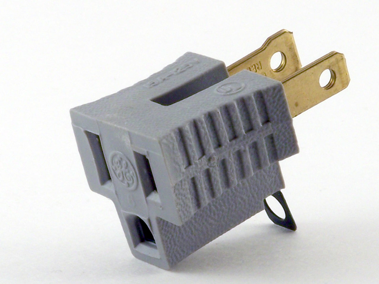
I put the iso tranny on my Silvertone. Before I installed it, I strategically placed an adapter on the plug that allows it to pug in to the wall in only one direction, aka polarized, ensuring the neutral was the one on the chassis. The old amps came with non-polarized plugs. W/O that polarizing adapter, it's a 50-50 chance you will have the hot going to the chassis. It's a temporary way to increase the safety somewhat.
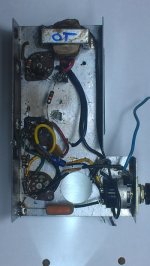
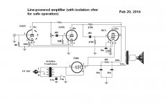
Thanks for the safety tips. I have added a 2.5A 120/120 xfmr to my bench with a female 3-prong AC socket, so I have no excuse for not protecting myself. Oh, and that was before I posted a thread in the Hi-Fi area, but not showing it on a schematic, so yes it got deleted (and I was directed to Note #2). All good, I want to learn from other's mistakes! Anyway, I'm trying to squeeze as much headroom out of this amp, and with so little plate voltage I am now learning how to use the tube data sheet plate characteristics graphs, draw load lines, and optimize voltage swing to input signal. Below is my current amp, with 1/2 a 12AU7 added to the original intercom. Yes, it has only 16v on the plate. Not even on the tube graph... The amp clips, not sure where (2nd or 3rd stage). Will boost B+ where I can, play with load resistors, and set bias between grid and plate cutoff points. Or, put a $25 Weber WRVBPT (260VAC sec) on it! Only has 6.3v for filaments, so will need to find other tubes....
Attachments
I would put the power switch on the hot leg of the primary side of the iso tranny. Otherwise there would be 120v on the tranny when it is off. Assuming the cap is on the switch to avoid a "pop" that cap won't be needed with the switch moved. I guess it was a noise filter but is no longer needed. A fuse should be used between the hot leg from the wall and the switch. 1amp slow blow should be fine.
My iso tranny has 133vac on it's secondary when running since the actual load is not the full rated amount. So I'm getting 8% more PS volts which is good. I reduced the heater current back to spec by increasing the heater-dropping-resistor in my setup. 3 prong main of course.
Have you measured the gain of each preamp stage? (ac volts out / ac volts in)
"Have you measured the gain of each preamp stage? (ac volts out / ac volts in)"
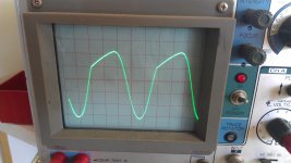
jjman - I have just started doing just that, but using my scope, with a "guitar-level" 150mVp-p 1KHz from my SigGen. I just can't get used to preamp tubes working with only 16 VDC on their plates!! You notice I did add a 12AU7 to get more gain (and clipping to then control), so was able to eliminate the 300R heater dropper. Tube filaments are real close to desired. I did move the preamp (12AU7 & 12AT6) tubes B+ from pin 6 to 7 (on 50C5) to raise B+. Bad move.... Didn't move any voltages more than +/- 5VDC, but the amp was way squawky over 5 on vol pot. Reversed the change, and am back to (with 150mVp-p signal) 4.6Vp-p out of 12AU7, 32Vp-p from 12AT6, and 215Vp-p from the 50C5 (is this way too high, for 125VDC on 50C5's plate?).....Need to read up on AC signal voltage swings, gain and plate voltage.....and check my scope cal.
jjman - I have just started doing just that, but using my scope, with a "guitar-level" 150mVp-p 1KHz from my SigGen. I just can't get used to preamp tubes working with only 16 VDC on their plates!! You notice I did add a 12AU7 to get more gain (and clipping to then control), so was able to eliminate the 300R heater dropper. Tube filaments are real close to desired. I did move the preamp (12AU7 & 12AT6) tubes B+ from pin 6 to 7 (on 50C5) to raise B+. Bad move.... Didn't move any voltages more than +/- 5VDC, but the amp was way squawky over 5 on vol pot. Reversed the change, and am back to (with 150mVp-p signal) 4.6Vp-p out of 12AU7, 32Vp-p from 12AT6, and 215Vp-p from the 50C5 (is this way too high, for 125VDC on 50C5's plate?).....Need to read up on AC signal voltage swings, gain and plate voltage.....and check my scope cal.
Only has 6.3v for filaments, so will need to find other tubes....
12at7, 12au7, 12ax7 can be wired fot 6.3v filaments.
Edit: just noticed12at6. Never mind.
All good, I want to learn from other's mistakes! Anyway, I'm trying to squeeze as much headroom out of this amp, and with so little plate voltage I am now learning how to use the tube data sheet plate characteristics graphs, draw load lines, and optimize voltage swing to input signal. Below is my current amp, with 1/2 a 12AU7 added to the original intercom. Yes, it has only 16v on the plate. Not even on the tube graph... The amp clips, not sure where (2nd or 3rd stage). Will boost B+ where I can, play with load resistors, and set bias between grid and plate cutoff points. Or, put a $25 Weber WRVBPT (260VAC sec) on it! Only has 6.3v for filaments, so will need to find other tubes....
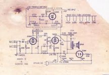
Are you working from a known working schematic? In the first post you said it's based on the Gregory, but your schematic looks quite different and has some really strange connections. Before commenting on the design, I just want to make sure I am looking at the right thing...
Yes, the original schematic (which I couldn't find, had to draw it) was what I posted earlier, minus the 1/2 12AU7 input stage. The "old intercom" had 3 tubes and heater dropping resistor. Replaced filter caps and it worked, but too clean, and wanted to push it to clipping. I used the Gregory schematic as a guide only (input tube is a 12AU6, not the AT6 I have). I'd like to add the Gregory tremelo later, how having a spare triode. Want to bias the 1st stage clean with headroom, and be able to push the 2nd stg to "dirty" with the vol pot (which was originally on the input jack before what was the 12AT6 1st stage!). The "strange connections" are original to the intercom (and probably the way I did the schematic...).
- Status
- This old topic is closed. If you want to reopen this topic, contact a moderator using the "Report Post" button.
- Home
- Live Sound
- Instruments and Amps
- Old Intercom guitar amp project