I see, then I recommed that you get rid of the 10M grid leak, so the 12AT6 is self-biased, you can set the gain and voltage swing using the RC coupling chart below. Disconnect the plate supplies for the 12AT6 and 12AU7 from the 35W4's screen grid, by tapping off the B+ supply via voltage dropping resistors, and adding some bypass capacitors, so somewhere around 90-100V appears on the plates. The coupling capacitor should be connected between the plate of 12AU7 and the gain pot.
An externally hosted image should be here but it was not working when we last tested it.
Jazbo- thanks for the amplifier chart. Is this for a 12AT6? Not on the Tung-Sol data sheet I have, but found a similar one for a 6C4-another low-mu triode. Will help a lot! And I think the dual 68K inputs was just a popular choice for dual-input amps, but is just asking to be modified, to easily provide a different amp response (gain, briteness, etc).
"Have you measured the gain of each preamp stage? (ac volts out / ac volts in)"
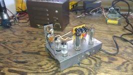
jjman - I have just started doing just that, but using my scope, with a "guitar-level" 150mVp-p 1KHz from my SigGen. I just can't get used to preamp tubes working with only 16 VDC on their plates!! You notice I did add a 12AU7 to get more gain (and clipping to then control), so was able to eliminate the 300R heater dropper. Tube filaments are real close to desired. I did move the preamp (12AU7 & 12AT6) tubes B+ from pin 6 to 7 (on 50C5) to raise B+. Bad move.... Didn't move any voltages more than +/- 5VDC, but the amp was way squawky over 5 on vol pot. Reversed the change, and am back to (with 150mVp-p signal) 4.6Vp-p out of 12AU7, 32Vp-p from 12AT6, and 215Vp-p from the 50C5 (is this way too high, for 125VDC on 50C5's plate?).....Need to read up on AC signal voltage swings, gain and plate voltage.....and check my scope cal.
Looks like gain is ~31 in stage 1 and ~7 in stage two with a total preamp of 213. That’s double the ~100 in my single stage 12au6. So you have likely increased gain despite the very low plate voltages currently present. If noise is not a problem it sounds like it worked out. 215Vp-p sounds ok for the 50c5 but I would look at the output voltage on a dummy load instead of the plate. Safer and reveals the output wattage with some math. With guitars putting out more than 150mv p-p, I bet you’ll see clipping on the output with closer to 500p-p input.
I love trem but I wonder if your power supply has more slack to give.
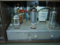
JJ- Thanks for confirming my signal/gain numbers look OK. I use a spkr/dummy switch box so I can crank this little guy (or a big guy) and not scare the dogs when using a SigGen.... Will check it there as well. And I see the Hi/Lo input strategy, with the top input it parallels the lower 68K with the 1M. That way lowers the grid leak R, attenuating the input signal (?). I will be modeling my tremelo on a Gregory amp (see pic), which uses the came tube complement (except for a lower-mu 12AU6 instead of the 12AT6 in my amp). Having added a twin triode 12AU7 I have a triode to spare. I think my only limitation on B+ is the iso xfmr (2.5A).... Can always add another 133V B+ feed with another filter/decoupling electrolytic...? The 35W4 is rated 660mA plate.
Attachments
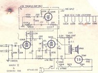
Correct me if i'm wrong but 68k parallelled with 1 meg is only 63k, way too low an input impedance for a guitar to be plugged into the top input with the bottom input connected to ground. The way i see it, you plug into the bottom input if there's only 1 guitar and if there's two of you, you also plug into the top input. The 68k resistors just sum the two guitar inputs and they still see an input impedance of 1.068 meg.
Edit: a single guitar plugged into the top input would see an input impedance of 68k + 68k || 1 meg which is 131k
Edit: a single guitar plugged into the top input would see an input impedance of 68k + 68k || 1 meg which is 131k
Last edited:
Yes,
The top input is the low sensitivity input, guitar signal is divided by 2 by the 2 off 68K plus (as you say) the output from the guitar may be lower due to the loading effect of that 68K. This may well be dependent upon the guitars volume control setting which will affect the source impedance.
Cheers,
Ian.
The bottom input is the High Sensitivity setting where you have the "traditional" 68K grid stop and 1M grid leak.
Update: Have to give up on the added 9-pin 12AU7...got the gain I wanted, but can't use the other 1/2 as a tremelo osc (mu too low), and didn't want to go the hi/lo mu dual triode route. So have a little chip tremelo I built (using the Weber circuit with some tweaks), and will replace the 12AU7 with a 12AT6 (to keep all the tubes 7-pin). Wanted to play with a little SS tremolo, as a future add-on to any amp. I like it! Doesn't affect the "tube sound", and is way flexible, and power reqm'ts are miniscule.... Will keep the little 4" spkr that fits inside the case, with a 1/4"jack that allows a bigger cab, so the amp can flex it's tiny but mighty 4.3W of plate dissipation muscle!. Be my smallest tube amp build to date.
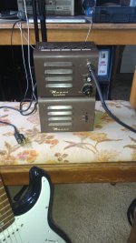
FINAL: My Masco amp "stack"!
Finally done with this little intercom project! Added a 12AT6, getting 4.3W plate diss, has a matching "cab" with a 4" spkr (but can push a 12"), Weber SS vibrato board (variable speed knob up front, fixed intensity). Do they have contests for "weirdest" amp builds? Would this get maybe an honorable mention? Well, this is as small a build as I want to do (my first was a champ clone in a Squire cab), and I want to go BIG now (always liked that Sun Coliseum bass amp...). Will keep you all posted, and THANKS for all the help and ideas!
Finally done with this little intercom project! Added a 12AT6, getting 4.3W plate diss, has a matching "cab" with a 4" spkr (but can push a 12"), Weber SS vibrato board (variable speed knob up front, fixed intensity). Do they have contests for "weirdest" amp builds? Would this get maybe an honorable mention? Well, this is as small a build as I want to do (my first was a champ clone in a Squire cab), and I want to go BIG now (always liked that Sun Coliseum bass amp...). Will keep you all posted, and THANKS for all the help and ideas!
Attachments
- Status
- This old topic is closed. If you want to reopen this topic, contact a moderator using the "Report Post" button.
- Home
- Live Sound
- Instruments and Amps
- Old Intercom guitar amp project