Hello everyone, I hope this isn't too much of a newbie question, but I need some advice on an input stage I am trying to build.
Basically I am trying to build an input stage that can accept either an unbalanced input (from a guitar) using a mono TS cable or a balanced input from my effects processor using a stereo 1/4 inch TRS cable.
The single output of the receiver will drive various different effects pedals depending on how I set up my looper.
I have built a very basic circuit using a to ina134 based on figure 1 of the dats sheet
http://www.ti.com/lit/ds/symlink/ina134.pdf
So far I have tested only with an unbalanced input ie my guitar tip connected to the hot input and the cold input tied to ground.
My problem is that the circuit is giving me some attenuation and is colouring the guitar signal, making it sound a little muddy or muffled.
I have built a very nice sounding buffer which on its own works great, but even if a put this after the receiver CCT, the problem exists.
I wondered if the basic receiver CCT I am using is not suited to the hi-z guitar output or if I am simply using too basic a receiver CCT.
Does anyone have any thoughts or experience with a similar problem, as you can probably tell, my audio electronics expertise could fit in a match box without taking the matches out first so apologies if this is a dumb question, be gentle with me")
Basically I am trying to build an input stage that can accept either an unbalanced input (from a guitar) using a mono TS cable or a balanced input from my effects processor using a stereo 1/4 inch TRS cable.
The single output of the receiver will drive various different effects pedals depending on how I set up my looper.
I have built a very basic circuit using a to ina134 based on figure 1 of the dats sheet
http://www.ti.com/lit/ds/symlink/ina134.pdf
So far I have tested only with an unbalanced input ie my guitar tip connected to the hot input and the cold input tied to ground.
My problem is that the circuit is giving me some attenuation and is colouring the guitar signal, making it sound a little muddy or muffled.
I have built a very nice sounding buffer which on its own works great, but even if a put this after the receiver CCT, the problem exists.
I wondered if the basic receiver CCT I am using is not suited to the hi-z guitar output or if I am simply using too basic a receiver CCT.
Does anyone have any thoughts or experience with a similar problem, as you can probably tell, my audio electronics expertise could fit in a match box without taking the matches out first so apologies if this is a dumb question, be gentle with me
the balanced input has two signal pins (inputs) and one Chassis pin.
A standard balanced interconnect matches this perfectly.
An unbalanced interconnect will attach to the two signal pins. pin 2 is signal Hot. Pin 3 is signal ground/return. You need to add a manual switch that shorts pin3 to audio ground inside the balanced receiver.
That makes your bal/unbal receiver compatible with both types of Source.
But you have TS and TRS cables. The ring is pin3 and the TS does not have the ring. Problem ! Do you modify your TS source to make it a TRS? Your decision. I'd suggest you DON'T modify your guitar TS plug.
The guitar needs is own receiver circuit. Use what you have, but fit a trs output to that circuit. It won't now be compatible with TR inputs. Label it as such.
your guitar connected directly needs a hi-z input
your effects may work ok with less
only your processor or other PA gear needs the bal/se converter, and this will not need the guitar hi-z input at all
but isn't it most common now to use the effects as pre stage between guitar and amp ?
you want the pedals on the floor where you stand, and makes little sense to use long loop cables
you can get small pre/gain/booster 'effect pedals', and they are often basicly just a small hi-z preamp
Thanks tinitus that makes sense, I just tried the circuit with a hi-z buffer in front of it and definitely the receiver was being loaded down by the guitar pickups.
I am going to try building the instrument amplifier version shown on the ti data sheet, do you think this will work? My goal is to make an input stage that allows me to plug in either the guitar or a balanced output from an effects unit without having to use separate inputs or a switch.
I am going to try building the instrument amplifier version shown on the ti data sheet, do you think this will work? My goal is to make an input stage that allows me to plug in either the guitar or a balanced output from an effects unit without having to use separate inputs or a switch.
I'm not sure
depends on your setup
I do not use any effects for my bass, so I need amp with hi-z input
but if you use effect pedals with hi-z input, then your amp wont need a very hi-z input
but most pedals are still designed for relatively high input z
maybe 100k will do, and your BAL/SE receiver may just do that perfectly, or maybe less will do
and you can give you amp a second hi'z input jack for direct connect
but when it comes to BAL/SE converting you better listen to Andrew
I have been tempted to try some PA gear, but everything is mostly balanced, and I gave up on it, so far ...
I added the 1 meg resistor from above but it didn't seem to help. Have some parts on order to build the instrumentation amp CCT from the data sheet, hoping this will work.
maybe the chip does not have hi-z input
@ Bigtim1966
The 1 Meg resistor should have worked ? If you could draw a circuit of what you've done so far, & what you're proposing, it would assist us better in helping you
We've no idea what circuit he's using, and assuming it's too low an input impedance?, then reducing it further (even if only slightly) by adding an extra 1meg in parallel will only make it worse.
Presumably you were assuming he's blindly copied the partial circuit from the datasheet?, which makes no pretence of been a full working circuit.
As you say, and as always, the OP need to post EXACTLY what circuit he's built.
I will do a sketch, but in fact Nigel is right, my receiver circuit is nothing more than the figure from the data sheet, so just the ina134 and a couple of 1uf caps on the +\- supplies. And my next step was to add the two additional amps to make the instrument amplifier from the data sheet.
I have a bad feeling I am out of my depth if there is additional circuitry to be designed around these basic figures from the datasheet
I have a bad feeling I am out of my depth if there is additional circuitry to be designed around these basic figures from the datasheet
Originally Posted by Nigel Goodwin
assuming it's too low an input impedance?, then reducing it further (even if only slightly) by adding an extra 1meg in parallel will only make it worse.
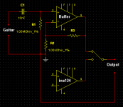
Hi, i was talking about putting a 1 Meg in parallel with the Positive input of the Buffer OpAmp he said he was going to use, which would better match the guitar. I wasn't suggesting connecting the 1 Meg to the ina134 circiut.
@ Bigtim1966
See my screenie for more details. Power supply connections not shown, as i'm guessing you know how to do that? ina134 details not shown, as you have the PDF for those.
Attachments
in this case it is my understanding the 1M is a safety resistor, should input be disconnected
or it could be a pulldown resistor if impedance is too high ... but you can't raise it, unless maybe you also attenuate the signal
and maybe the chip could be only 50K (still missing a number ?)
or it could be a pulldown resistor if impedance is too high ... but you can't raise it, unless maybe you also attenuate the signal
and maybe the chip could be only 50K
(still missing a number ?)It is not possible to do what you want with INA134 because the resistors are already inside the chip, therefore the input impedance will always be 25k or less.
You need to make a differential amplifier based around an op-amp with 1 meg resistors on the inverting side and 510k on the noninverting side. The problem here is that in the balanced mode the performance will be compromised by the high value resistors.
You need to make a differential amplifier based around an op-amp with 1 meg resistors on the inverting side and 510k on the noninverting side. The problem here is that in the balanced mode the performance will be compromised by the high value resistors.
I have a bad feeling I am out of my depth if there is additional circuitry to be designed around these basic figures from the datasheet
Datasheets generally don't give you working practical circuits, they only give you the absolute basic minimum you require in order to design a working circuit - although there are occasionally full working examples.
I wondered if the basic receiver CCT I am using is not suited to the hi-z guitar output or if I am simply using too basic a receiver CCT.
you got the answer what now ?
- Status
- This old topic is closed. If you want to reopen this topic, contact a moderator using the "Report Post" button.
- Home
- Live Sound
- Instruments and Amps
- Balanced/unbalanced line receiver