This probably isn't the most exciting of projects, but I thought I'd share since I'm working on it.
I'm a freshman in college (majoring in EE) and I'm on Christmas break right now. I've decided to take up guitar. I bought a cheap Strat the other day, but now I need something to play it through...so I decided to roll my own amp.
Most of the parts are still in transit. It actually wound up being more than I was anticipating, around $85, since I had to source parts from 4 different online vendors.
The amplifier electronics are based off of the Noisy Cricket, which is based off of the widely known Ruby amp.
The general specifications are ->
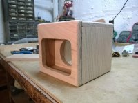
.: 1.0 cubic ft cabinet
.: Oak and steel construction
.: 3" FaitalPRO driver
.: LM386N-3 chipamp
.: JFET preamp
.: Gain, Tone, and Volume Controls
.: Internal AC-DC Power Supply (12V)
The style of the amplifier is based off of the vintage 50s and 60s Fender tweed amplifiers, though I won't be wrapping it in tweed because it's fairly expensive. Here's one model in particular that my design has taken from.

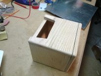
Anyway, this is just a preliminary post. Any feedback is appreciated. Attached is my current progress.
I'm a freshman in college (majoring in EE) and I'm on Christmas break right now. I've decided to take up guitar. I bought a cheap Strat the other day, but now I need something to play it through...so I decided to roll my own amp.
Most of the parts are still in transit. It actually wound up being more than I was anticipating, around $85, since I had to source parts from 4 different online vendors.
The amplifier electronics are based off of the Noisy Cricket, which is based off of the widely known Ruby amp.
The general specifications are ->
.: 1.0 cubic ft cabinet
.: Oak and steel construction
.: 3" FaitalPRO driver
.: LM386N-3 chipamp
.: JFET preamp
.: Gain, Tone, and Volume Controls
.: Internal AC-DC Power Supply (12V)
The style of the amplifier is based off of the vintage 50s and 60s Fender tweed amplifiers, though I won't be wrapping it in tweed because it's fairly expensive. Here's one model in particular that my design has taken from.
Anyway, this is just a preliminary post. Any feedback is appreciated. Attached is my current progress.
Attachments
Beautiful build, congratulations.
And a Cricket is fine to start.
Later maybe you can put a louder amp there (10/15W) but I congratulate you on going step by step.
And choosing a Pro driver such as the Faital Pro is an excellent choice.
Most small/simple amps suffer from using cheap horrible speakers.
Keep us up to date on your advances")
And a Cricket is fine to start.
Later maybe you can put a louder amp there (10/15W) but I congratulate you on going step by step.
And choosing a Pro driver such as the Faital Pro is an excellent choice.
Most small/simple amps suffer from using cheap horrible speakers.
Keep us up to date on your advances
Beautiful build, congratulations.
And a Cricket is fine to start.
Later maybe you can put a louder amp there (10/15W) but I congratulate you on going step by step.
And choosing a Pro driver such as the Faital Pro is an excellent choice.
Most small/simple amps suffer from using cheap horrible speakers.
Keep us up to date on your advances
Thanks for your kind words.
As far as the driver goes, I was initially going to spend less, around $5, but since my amp is a little underpowered at 1W maximum, I decided to match the speaker to get the most out of the amp, without killing it. Using the LM386N-3 @ 12V paired to a 16ohm driver seems like a good deal since (This is all according to the 386 datasheet graphs.) The Faital driver has a sensitivity of 91db/W, which is crucial for a low power amp.
Thanks again.
If anyone's looking at this thread,
If I'm going to have the mains toggle on/off switch attached to a metal panel that is also connected to the other controls, would it be necessary to ground that panel to safety earth?
I was just curious because if the switch somehow failed and its bushing/bat became live, then it would surely mess up the rest of the electronics I suspect.
In theory, if the metal panel was live and safety earth was attached to it, would it save my electronics and speaker from destruction? The mains input is fused of course.
Absolutely connect that safety ground to the front panel as well, the life you save might be your own. I've encountered just a couple of switches that failed and shorted internally to their metallic bats, the particular amplifiers were not grounded except through the RCA cables which must have saved the owner's life because he commented that plugging the amps in one way versus the other always resulted in a blown fuse.
Uh oh...
So I'm running into some problems with the electronics. After several hours of meticulously soldering everything on a perfboard...I'm experiencing some issues.
1.) After hooking up my guitar, I don't hear the guitar at all through the amp.
2.) However, I do hear a local Spanish radio station fairly loud.
3.) If I hook up my phone and play audio through it, it comes through very quiet. (i.e. My phone is louder alone.) The radio still prevails.
4.) All of the controls seem to be working correctly. The volume works, and the other two seem to work alright, as well as the "grit" switch.
5.) Connecting the amp ground to earth (through my body) silences some of the noise, but it still is very quiet.
I've switched out both the FET and the LM386 for new parts just in case. That did nothing.
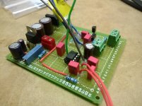
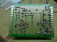
I've built a 386 amp before and I've also had some problems. I'm not quite sure what's going on. I've rechecked my wiring and everything seems to be correct. I took a lot of time to make sure I made good mechanical connections. Perhaps my grounding scheme is not too good? If you look at the picture, the ground "rail" is the long strip of copper wire that runs in a horseshoe shape on the bottom of the board.
Perhaps something is oscillating? I'm not sure.
Some people talk of putting a small decoupling capacitor near the LM386 chip itself. My power supply is pretty solid and there shouldn't be any voltage sag because it's regulated.
Any ideas?
Thank you.
So I'm running into some problems with the electronics. After several hours of meticulously soldering everything on a perfboard...I'm experiencing some issues.
1.) After hooking up my guitar, I don't hear the guitar at all through the amp.
2.) However, I do hear a local Spanish radio station fairly loud.
3.) If I hook up my phone and play audio through it, it comes through very quiet. (i.e. My phone is louder alone.) The radio still prevails.
4.) All of the controls seem to be working correctly. The volume works, and the other two seem to work alright, as well as the "grit" switch.
5.) Connecting the amp ground to earth (through my body) silences some of the noise, but it still is very quiet.
I've switched out both the FET and the LM386 for new parts just in case. That did nothing.
I've built a 386 amp before and I've also had some problems. I'm not quite sure what's going on. I've rechecked my wiring and everything seems to be correct. I took a lot of time to make sure I made good mechanical connections. Perhaps my grounding scheme is not too good? If you look at the picture, the ground "rail" is the long strip of copper wire that runs in a horseshoe shape on the bottom of the board.
Perhaps something is oscillating? I'm not sure.
Some people talk of putting a small decoupling capacitor near the LM386 chip itself. My power supply is pretty solid and there shouldn't be any voltage sag because it's regulated.
Any ideas?
Thank you.
Attachments
Hi TimNJ,
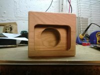
congratulations on the woodwork, it looks very nice. I was also a bit surprised at the "recessed baffle" but since you say it's just a mockup, then yeah, move it forward a bit. What's the speaker size? 5 inch? Don't expect too much bass...
Anyway, pertaining to your original question in the last post about the RF interference and Cap near the chip, it isn't because the voltage will sag. Actually, there are two caps that should be installed next to it, first and foremost a parasitic elimination cap (in the order of 0.05 to 0.001uF) and an electrolytic filter cap, or supply cap in the order of 1 to 100uF, depending on how far the IC is located from the supply and the amount of current it draws. I do not have formulas for you but as general rule you want a couple uF for the electrolytic and a couple nF for the parasitic filter cap. Yes, I know, your regulator is only two and a half inches away from your IC, but have you considered the effect of inductance of the "traces" (in this case, pieces of wire)? The inductance will act as a filter network with the caps and if you have no cap at the load (be it an IC or a transistor or a tube) you will no longer have a PI filter, which is what you want. In say, a Marshall or Fender amplifier, you have a power supply, filtered by an electrolytic, going to the power amp section, then a series resistor of about 1kohm or so, then another electrolytic going to the phase inverter. What the loads are is unimportant for the sake of this discussion, it is the PI filter (named so because the components are laid out in the shape of the greek letter Pi) that I wanted to explain here. A much better explanation is available in textbooks such as Malvino's Electronic Fundamantals and others, and also on the fabled "internet".
We'd be better suited to help if we might see the schematic you were using.
Cheers,
and add those caps!
gain-wire
- Status
- This old topic is closed. If you want to reopen this topic, contact a moderator using the "Report Post" button.
- Home
- Live Sound
- Instruments and Amps
- Small "Vintage" Guitar Amp Build