Here's a photo of my progress so far. The chassis box turned out to be a little small so I'm having one made up for me. Anyhow, will the diodes cause any noise issues being placed on the main board like that?
I've built several amps from premade chassis and premade eyelet boards, with easy to follow layouts (Fenders & a Marshall), but this is the first one that I've created a layout for and built my own boards[and will be drilling the chassis too].
How's it look so far?
I've built several amps from premade chassis and premade eyelet boards, with easy to follow layouts (Fenders & a Marshall), but this is the first one that I've created a layout for and built my own boards[and will be drilling the chassis too].
How's it look so far?
An externally hosted image should be here but it was not working when we last tested it.
Single 30 uF is fine. Screen resistors limit the current to the screens when the amp is driven hard. The plate voltage on the output tubes drops with a large signal and the screen is more positive than the plate. This attracts more electrons causing more current to flow in the screens. The resistor causes a voltage drop lowering the difference between the plate and screen hopefully preventing burning up the screens. Older amps did not have them but then again the designers did not think we were going to overdrive the amps.ok here's an updated drawing.
As for the power tube screen resistors, can anyone help me understand what their function is?
Plus, I'm looking at C2 & C3. Any reason not to just use a single 30uF or just drop the 10uF?
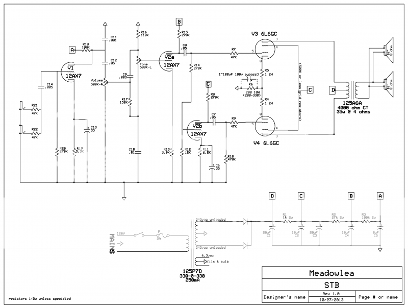
Single 30 uF is fine. Screen resistors limit the current to the screens when the amp is driven hard. The plate voltage on the output tubes drops with a large signal and the screen is more positive than the plate. This attracts more electrons causing more current to flow in the screens. The resistor causes a voltage drop lowering the difference between the plate and screen hopefully preventing burning up the screens. Older amps did not have them but then again the designers did not think we were going to overdrive the amps.
Thank you very much for the insight.
I checked against a couple other 6L6 schematics and they used 1w resistors so that's what I got for it.
- Status
- This old topic is closed. If you want to reopen this topic, contact a moderator using the "Report Post" button.