Hey all - new around here.
I've been fooling around with tube radios/phonos and amps for a few years now, and I'm about to undertake my first "from scratch" build for a good friend. A few disclaimers before we get started:
-I don't actually play the guitar (I'm a drummer).
-I know my way around a schematic, but an EE I'm not.
-I've already ordered all the goodies, so don't bother with any "you don't want to build that amp!" replies.
-My first kiddo is due any day now, so if I happen to disappear from the forum during a crucial moment in the build, it's not personal.
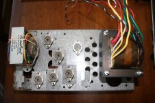
My buddy wants a Marshall 18 Watt clone. I'm only building the head unit... he's building a 2x12 cab for the "business end". Here's the interesting part: I'm building the amp into the chassis of an old power inverter he picked up for $5 at a garage sale...


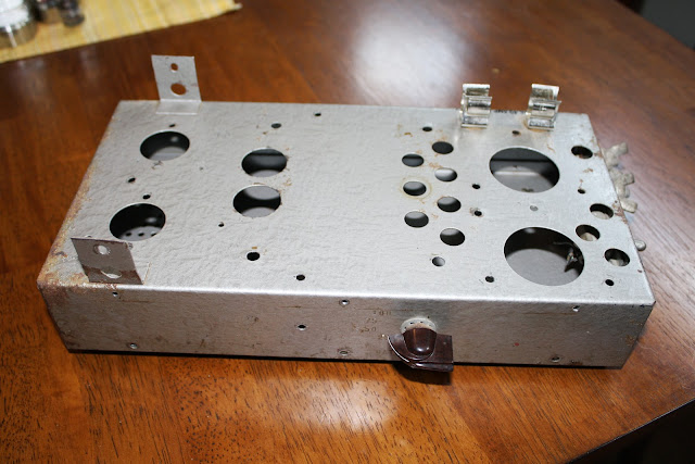
I gutted the 'ol boy, but as you can see, it's going to be TIGHT in there. I'm thinking of plugging all the holes so I can at least start fresh with the top of the amp. Since all the sides of the chassis will be exposed, I'll have to run all 6 tubes and the transformers out the top, and then try to squeeze the entire circuit underneath.
What do I need to look out for re: proximity of tubes to other components, etc? Any potential safety issues with the metal chassis?
Looking forward to getting started!
-Mike
I've been fooling around with tube radios/phonos and amps for a few years now, and I'm about to undertake my first "from scratch" build for a good friend. A few disclaimers before we get started:
-I don't actually play the guitar (I'm a drummer).
-I know my way around a schematic, but an EE I'm not.
-I've already ordered all the goodies, so don't bother with any "you don't want to build that amp!" replies.
-My first kiddo is due any day now, so if I happen to disappear from the forum during a crucial moment in the build, it's not personal.
An externally hosted image should be here but it was not working when we last tested it.
My buddy wants a Marshall 18 Watt clone. I'm only building the head unit... he's building a 2x12 cab for the "business end". Here's the interesting part: I'm building the amp into the chassis of an old power inverter he picked up for $5 at a garage sale...
I gutted the 'ol boy, but as you can see, it's going to be TIGHT in there. I'm thinking of plugging all the holes so I can at least start fresh with the top of the amp. Since all the sides of the chassis will be exposed, I'll have to run all 6 tubes and the transformers out the top, and then try to squeeze the entire circuit underneath.
What do I need to look out for re: proximity of tubes to other components, etc? Any potential safety issues with the metal chassis?
Looking forward to getting started!
-Mike

Thanks for the replies... I've actually caved to using a turretboard for this to save time and make this thing bulletproof, so I do think I'll be OK. Just need to watch myself as I do the layout.Which 18 Watt circuit? Looks like plenty of room, well OK, enough room unless you are real sloppy with the wiring.
I'm using a standard 18 Watt schemo w/ the trem. circuit.
Any extra safety measures I should build into this badboy, given that the whole thing is essentially a giant steel lunchbox?
-Mike
With the B+, eh? I've never seen this before. What is the idea... to protect the OT in case of a short?What you might want to do, and I think it is good practice, is put a 0.25A fuse in series with the B+.
-Mike
Look up some info about good layout of heater wires. And there's some resistors that are best soldered directly to the tube sockets. Keep the power transformer far away from the guitar input and high-gain preamp section. Place the power transformer far away from the output transformer and don't orient them in the same direction.
Good luck and have fun.
Good luck and have fun.
Already having a blast. DIY presents a different set of challenges than restoration, but I'm learning a lot of great things about these circuits from trying my hand at this. This forum is packed with great info, glad I found my way back.
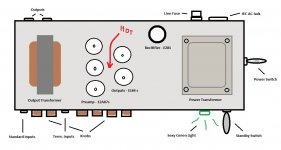
I put together this extremely technical diagram of my proposed layout this morning (see attachment). Thoughts? Please note that this drawing is not to scale with anything, including itself...
-Mike
I put together this extremely technical diagram of my proposed layout this morning (see attachment). Thoughts? Please note that this drawing is not to scale with anything, including itself...
-Mike
Attachments
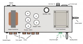
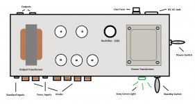
To understand the heat issues it helps to consider both the radiated and convected heat. Most designs let the output tubes radiate heat out the back and have a vent in the top above the outputs (at least Marshall/VOX and other makes with the chassis at the bottom). You might want additional venting and radiating area (like drilling out the holes a little larger by the output tubes) or a fan. Pics don't show the top; is it perforated too? Tinitus' conventional layout also puts the preamp tubes near the knobs.
If you're using turret boards you might use two, one for the preamp and another for the power amp. Or even a third one for the power supply.
Personally, I would put the transformers at even more extreme ends, and probably leave only 1/4 inch between them and the perf cover. Your case looks deeper relative to its length, so if you draw to scale you might prefer to put the output transformer to the extreme back and put the preamp tubes in a row that starts in front of the OT, even closer to the inputs and away from the power transformer and power supply.
Last edited:
Also plan where you're going to put the large filter capacitors.
Take a good look at the schematics Tinitus linked to. In tight space and limited budged, I advise you consider a good one-channel amp instead of the two-channel amp you drew. If you want more versatility, add a stage that switches in/out, possibly via footswitch relay.
Take a good look at the schematics Tinitus linked to. In tight space and limited budged, I advise you consider a good one-channel amp instead of the two-channel amp you drew. If you want more versatility, add a stage that switches in/out, possibly via footswitch relay.
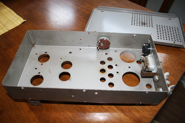
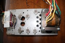
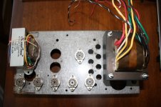
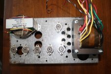
Thanks for the thoughts, all. Rather than try and work up a scale drawing, I snapped a few photos with the components -generally- in place. I still need to plug the holes in the chassis. I think layout 3 seems best... plenty of room for the input jacks, tubes spaced relatively evenly, and enough room leftover to house the filter caps up top if it comes to that.
-Mike
-Mike
Attachments
No perforation along the top... only the sides and bottom. A small, quiet fan might be in order.You might want additional venting and radiating area (like drilling out the holes a little larger by the output tubes) or a fan. Pics don't show the top; is it perforated too?
-Mike

- Status
- This old topic is closed. If you want to reopen this topic, contact a moderator using the "Report Post" button.
- Home
- Live Sound
- Instruments and Amps
- Introductions/18 Watt Clone