Hi to all!
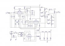
I've planning to build this preamp shown in PDF attached. In theory the desingn is pretty cool, I'm think... The original ideia is using 2 double triodes Tungsram's ECC83 (ECC 83S by JJ, 12AX7 LPS by Sovtek). Both clean and Lead Mode share the first triode of one ECC83 and the Lead mode use Cathode Follower. The diodes are optionally can be switched to add a typical saturation of a semiconductor and the sound is little harder. I'm hope this preamp works fine. I'm want to know the opinion of the DIYers for the circuit desing and any suggestios are wellcome!
my best regards,
Fernando M.
Attachments
 All musical instrument threads belong in Instruments and Amps per the below:
Tubes / Valves All about our sweet vacuum tubesThreads about Musical Instrument Amps of all kinds should be in the Instruments & Amps forum
Instruments and Amps Everything that makes music, Especially including instrument amps.
Moved...
Looks good.
The idea of adding semiconductor distortion to a tube input stage is very interesting! I have been playing around with adding tube distortion to semiconductor output stages and now I see that it is also done the other way round.
Hi,
The original idea to adding diodes for distortion is based on MesaBoogie's VTwin, but I'm design the circuit above to appreciate the sound of tubes, so the MesaBoogie's design uses TI TL072 Operational Amp.
[]'s
Fernando M.
Your tone controls, but more importantly, you output is going to react very different depending on the channel (lead/clean) you chose. One is taken from the anode and the other from the cathode (follower). The output impedance from these arrangements are totally different. You could consider adding an extra tube to act as a buffer for the clean channel and output.
Hi,
Thanks for sugestions, I'm not attepmted about differerences of impedances in clean/lead modes. So I'm add one more tube and using 2 cathode followers, 1 for clean and for the lead stay as shown above. I'll modify this design to looks better!
[]'s
Fernando M.
Thanks for sugestions, I'm not attepmted about differerences of impedances in clean/lead modes. So I'm add one more tube and using 2 cathode followers, 1 for clean and for the lead stay as shown above. I'll modify this design to looks better!
[]'s
Fernando M.
Last edited:
Hi Guys
You'll find the plate-driven EQ is much more dynamic and the controls will seem to do something. Cathode-driven EQs tend to lack control. TUT6 explains this in detail.
Clipping the output of the first stage is similar to the Poor Man's Overdrive in TUT. There a single diode pair was used and the resulting distortion is mild at best. Using three diodes each way, as the bridge+diode presents, will produce even less distortion. Unless you want the clean channel to be significantly louder and/or noisier and/or to have more tube character than the lead channel and/or you want a very low output all-around, , then you are best advised to convert the CF into a real gain stage. Move the diodes to the output of the (now) third stage of the lead path and make them switchable. Add an interstage attenuator between the 2nd and 3rd stages to avoid grid rectification. Now you have effectively the Ultra-low-noise version of the LPSP from TUT.
Have fun
Kevin O'Connor
- Status
- This old topic is closed. If you want to reopen this topic, contact a moderator using the "Report Post" button.
- Home
- Live Sound
- Instruments and Amps
- Guitar Tube Preamp