Hi all. I’m a beginner in analog, discrete builds, and I’d like some help. I’ve been studying various sites and forums, and have been learning LTSpice, and while I’ve made some good progress, there are a couple of things that have me stumped.
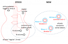
This is a project for an onboard preamp for a 2-pickup guitar. The stock guitar has a 3-way pickup selector (neck only, bridge only, both), a separate volume control for each pickup, then a common tone (treble rolloff) pot, and then the master volume. All passive.
I’d like to replace the two pickup volume pots with concentric, so each pickup would have its own bass and treble, boost and cut for each band, with flat in the middle. From there, on to a blend control, varying signal balance from 0/1 through 0.5/0.5, to 1/0. Then the combined signal goes to a midrange boost/cut, and finally to volume and out.
I’ve simulated the guitar pickups, but also have setup just a pair of AC sources, which I sim from 20-20k. The pickup sims generate a pretty characteristic guitar frequency profile, but for testing purposes I’ve been using the ACs, because they’re flat and it’s easier to see the effects of the various stages. Each pickup (I’m just going to call them A and B) is effectively one input channel, both having identical circuitry up to the blend, and from there it’s all common. Pickups are wired to the selector 3-way, where they’re either passed to the remaining circuitry or cut out. Each channel then has its own JFET buffer, gain adjusted to attain 0dB, and naturally transitioning the signal from low impedance to high impedance. All that’s working well in sim, when I build I’ll have to test and match those JFETs.
From there, on to the BassTreble stage. Each signal goes to Bass cut/boost, with its own opamp, then in series to Treble cut/boost, with its own opamp. I tried a bunch of Baxandall-type schemes, but didn’t like the interaction. My current scheme has none. Further downstream, the midrange cut/boost is the same thing again... they all are the same really, just with different resistor and cap values. The midrange stage passes through a volume pot to the final output buffer/booster - another JFET.
Oh yeah, this is all working off a 9V power (batteries). Due to the multiple opamps and their variable draws, I’m using a TLV2461 to keep my 4.5V steady.
That’s all working pretty good. It’s the blend that’s giving me grief. I just can’t get it to work. As a test, I input channel A with Bass at full boost, and B with Bass at full cut, then try to mix them. The result I’m expecting is for the output to look like A at one extreme, B at the other, and flat in the middle. No dice. Strange results. I’ve tried a number of schemes... JFET buffers for each channel, opamp buffers for each channel, simple “merge” blend, merge via opamp, merge to opamp with virtual earth, variously-placed caps and diodes to combat DC control and channel interference. Many didn’t work well (or at all). Those that did, all give the same shape of output. The output level depends upon which version I’ve used, but the shape is always the same. And I don’t understand why. And worse, I don’t know how to overcome it.
I can post the diagrams for all the other stages upon request (signal generation, input buffer, bass-treble cut/boost, midrange cut/boost, output buffer). But to try to keep it down, I’ll just post some of my results, and some of my blend stage attempts.
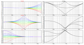
First, here’s some results for the three “tone” controls. On the left is each control varying “solo”, and on the right are various combinations (setting two controls and varying the third). I guess it’s one-pic-per-post, so the rest follow.....
This is a project for an onboard preamp for a 2-pickup guitar. The stock guitar has a 3-way pickup selector (neck only, bridge only, both), a separate volume control for each pickup, then a common tone (treble rolloff) pot, and then the master volume. All passive.
I’d like to replace the two pickup volume pots with concentric, so each pickup would have its own bass and treble, boost and cut for each band, with flat in the middle. From there, on to a blend control, varying signal balance from 0/1 through 0.5/0.5, to 1/0. Then the combined signal goes to a midrange boost/cut, and finally to volume and out.
I’ve simulated the guitar pickups, but also have setup just a pair of AC sources, which I sim from 20-20k. The pickup sims generate a pretty characteristic guitar frequency profile, but for testing purposes I’ve been using the ACs, because they’re flat and it’s easier to see the effects of the various stages. Each pickup (I’m just going to call them A and B) is effectively one input channel, both having identical circuitry up to the blend, and from there it’s all common. Pickups are wired to the selector 3-way, where they’re either passed to the remaining circuitry or cut out. Each channel then has its own JFET buffer, gain adjusted to attain 0dB, and naturally transitioning the signal from low impedance to high impedance. All that’s working well in sim, when I build I’ll have to test and match those JFETs.
From there, on to the BassTreble stage. Each signal goes to Bass cut/boost, with its own opamp, then in series to Treble cut/boost, with its own opamp. I tried a bunch of Baxandall-type schemes, but didn’t like the interaction. My current scheme has none. Further downstream, the midrange cut/boost is the same thing again... they all are the same really, just with different resistor and cap values. The midrange stage passes through a volume pot to the final output buffer/booster - another JFET.
Oh yeah, this is all working off a 9V power (batteries). Due to the multiple opamps and their variable draws, I’m using a TLV2461 to keep my 4.5V steady.
That’s all working pretty good. It’s the blend that’s giving me grief. I just can’t get it to work. As a test, I input channel A with Bass at full boost, and B with Bass at full cut, then try to mix them. The result I’m expecting is for the output to look like A at one extreme, B at the other, and flat in the middle. No dice. Strange results. I’ve tried a number of schemes... JFET buffers for each channel, opamp buffers for each channel, simple “merge” blend, merge via opamp, merge to opamp with virtual earth, variously-placed caps and diodes to combat DC control and channel interference. Many didn’t work well (or at all). Those that did, all give the same shape of output. The output level depends upon which version I’ve used, but the shape is always the same. And I don’t understand why. And worse, I don’t know how to overcome it.
I can post the diagrams for all the other stages upon request (signal generation, input buffer, bass-treble cut/boost, midrange cut/boost, output buffer). But to try to keep it down, I’ll just post some of my results, and some of my blend stage attempts.
First, here’s some results for the three “tone” controls. On the left is each control varying “solo”, and on the right are various combinations (setting two controls and varying the third). I guess it’s one-pic-per-post, so the rest follow.....
Attachments
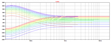
...and as for the blend stage, here’s the results of my attempts at attenuating the two channels, just prior to blending. The two channels vary simultaneously, from red through to purple. The sixth trace is the “flat”, when the controlling pot is at midpoint. Because I’m a beginner, I haven’t been able to figure out how to control the resistances to give equivalent variation on either side of center. So I’m anticipating that wiggling the pot around the middle will give a pretty “linear” balancing effect, while rotating it further towards one end or the other will roll off the “damped” channel faster and faster. Even though the signal sum will not always be exactly zero, I think it’s actually going to work out to be a pretty usable effect, so (for now) I’m happy with it. I’ve gotten very similar results with different arrangements... using a single pot as the actual blend point with output off the wiper, and using ganged pots in the feedback loops of buffer opamps.
Attachments
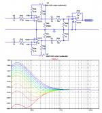
... and finally my blend results. This is pretty typical, with variations. I couldn’t figure out the curve at first, but then it hit me... the combination at any point looks like what would be the sum of the attenuated inputs ***for only their portions above 0db***. I tried to overcome this by boosting both signals 20dB, to put everything above 0dB. Same result. Same too with damping everything to sub-zero. As near as I can figure, the virtual-earth “mixing” opamp is cancelling out such changes, “bringing everything back” to zero. I tried a simple “merge” of the two channels without an opamp, which was pretty bad. I’ve tried the opamp in regular feedback mode, with a 4.5V bias, also not so hot.
So where do I go from here?
So where do I go from here?
Attachments
Why do you need the centre position to be flat frequency? I mean, most guitar preamps are based round the sound, not actual technical specifications. It seems pretty obvious you've got phase shift round your equaliser sections (to be expected), and that boost and cut are not summing to zero, but with the odd and obscure relationships of the harmonics coming off guitar pickups, that shouldn't be a problem.
On your schematic resistors R62 and R63 are only generating noise; I'd simplify, eliminate U1 and all the feedback gain clevers and just run your ganged pot (linear, I hope) as twinned volume controls, one turning up as the other is turned down; eliminates a couple of op amps worth of battery drain (assuming, of course that your equaliser section is low impedance drive). But there again I wouldn't have worried about interactions of the tone control sections; technically it might be there, but when you see the equaliser sections of a lot of the guitar amps considered 'great sound' you realise that they've been put together by trial and error rather than precisely equal boost and cut, or flat frequency response with pots centred.
If you are running a guitar pickup into a high impedance (which I assume to be the case) you are going to get a very harsh, high frequency rich signal. Generally the fact that the pickup itself is inductive, so its impedance rises with frequency, means that a lot of these highs vanish with the volume control (why the volume control's generally wired backwards, shorting out the coil; as you turn it down, the sound becomes mellower as well as quieter. Guitarists like this, at least the ones who use the volume control at anything but flat out or turned off do). So, to get a 'conventional' guitar tone, you generally need a lot more HF cut than boost, whatever this does to your noise figures (actually, you're generally fighting noise picked up by the pickups – lighting interference, mechanical microphony – far more than the ubiquitous white noise hiss). And an active guitar eliminates loads of losses and resonances in the nasty, capacitive screened cable (which at least means that the instrument sounds the same on a wide range of different guitar cables).
But an electric guitar is not a hi-fi source, so, rather than trying to get your circuit testing the way you'd expect, I suggest you wire it up as it's designed to be, then listen to the results. If it sounds good, you've won; if it doesn't, bodge.
Thanks, iaxxaxxai and chrispenycate, for the replies. All input is much appreciated! I’ll get to iaxxaxxai’s circuit and my results later, but first answer chrispenycate.
Thanks for the input. You’ve obviously got some experience with guitar preamps, so I look forward to your help. Yes, I’d like the centre position to be flat simply so that when the tone pots are centered, they neither add nor subtract from the pickups’ signals. I’ve been considering also the option of adding a switched bypass, so that I could go directly from the pickup buffers to the blend control. Either case eliminates or negates flattens the tone, which is something that many guitarists, myself included, like to have in a lot of situations. And yeah, there will be the expected phase shifts from the bass and treble sections, which is pretty unavoidable, and as you said, not really not much of a problem from a playing standpoint.
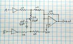
The schematic I posted was, admittedly, one of my more complex attempts at getting the blend to work. That’s a limb I crawled out on that didn’t really produce any improvements over the simpler ones. The general scheme I prefer you’ll see below... one pot modifying a voltage divider. Simple, and as effective as any other. Except for my previously-mentioned issue over balancing the modulation effects across the center. It seems I’ll always have a “slope” there, but as I’d said, that may not be much of an issue.
The notion of flattening really enters into my trying to ensure that I can blend between pickups, from 0:1 thru 0.5:0.5 and to 1:0, without any weird interference. The two channels’ input signals will be very similar, as they’re from two identical pickups sampling the same vibrating strings. Their difference is in the “flavor” granted by their physical positioning on the guitar. The bridge pickup will be brighter, with sharper attack, whereas the neck pickup will be mellower. The blend simply “balances” their contributions, lending a spectrum of tonal differences. The addition of individual bass and treble controls should expand that spectrum. My use of Abass1.0 and Bbass0.0 was simply a test of whether the blend circuit behaved neutrally – which it so far has not. The current situation shows the blend occurring variably according to frequency, which I think could and should be improved. I know this test will not get to true flat, because the gain and boost curves are not symmetrical, but I’d hope I can do better than what I’m getting now.
I agree 100%, that the frequency profiles of a lot of great amps are far from flat. Their characteristic curves are in fact what sets them apart, and their tones are desirable by many, if not most, guitarists. I’d like my preamp to be able to *not* color the signal if I so choose, to allow such downstream devices to do their thing unadultered. Yup, trial and error are going to rule at the end of the day. I just thought I’d try to start at “zero”.
I am in fact running my pickups into high impedance of JFET buffers. Their outputs feed the tone opamps, and those buffered signals are what I would pass to the blend circuit if I were to bypass the tone circuits. And yes, I expect that my final build will have to deal with (dampen) some pretty serious brightness. But I’d like to have a level playing field to start with, so that I can apply those tweaks intelligently and systematically.
And yeah, I know about the high-frequency variability of typical passive volume controls. Some like it, I don’t. I have a treble bleed on my master volume now, to combat that. What many people don’t realize is that with the very common setup of two separate passive pickup level controls (like my current stock setup), that the same thing is occurring for each of them. Also, interactions occur, increasingly so as either level gets very low. These reasons are one my three motivations for this project. The other two are increased tone flexibility and combating output cabling impedance, which you also mentioned.
You’re right – I’m going to have to build soon, and see what all this sounds like, and let my ear be the judge. But as I don’t have a bench full of components, and have been ordering in bits and pieces for the project, I’d just as soon try to firm this up before I start, so I at least can get my shopping list straight.
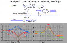
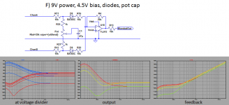
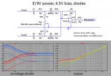
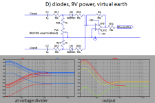
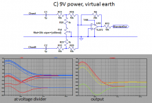
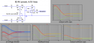
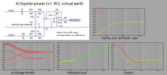
And now for iaxxaxxai . Here are some results I got. I wasn’t sure whether your triangles on the left were diodes or opamps (!!), so I figured you just meant these were the tone circuits’ opamps. I also wasn’t sure of the purpose of the 47uF cap at the pot wiper, so I tried it with and without. You’ll notice that I didn’t get very good results with it as you showed. I suspected some issues were from interference between A and B “crossing over” the junction of the blend and opamp feedback, so I tried some diodes there. I also tried using a virtual earth as well, as that’s what I’ve found recommended elsewhere (http://sound.westhost.com/articles/audio-mixing.htm and http://www.all-electric.com/schematic/simp_mix.htm). Those sources stated that inputs must be as close to 0V as possible, so I also tried capping the inputs. I also wondered whether the lack of contribution of the lower-amplitude frequencies was due to their dropping out of the opamp’s range, so I tried bipolar (+9/-9 V) power. I also wondered whether the effects I get are just in the bass spectrum, due to some filtering or some such, so I replace the bass/treble circuits with midrange. So see below.
Can either of you, or anybody else, tell me what’s causing this?
Thanks for the input. You’ve obviously got some experience with guitar preamps, so I look forward to your help. Yes, I’d like the centre position to be flat simply so that when the tone pots are centered, they neither add nor subtract from the pickups’ signals. I’ve been considering also the option of adding a switched bypass, so that I could go directly from the pickup buffers to the blend control. Either case eliminates or negates flattens the tone, which is something that many guitarists, myself included, like to have in a lot of situations. And yeah, there will be the expected phase shifts from the bass and treble sections, which is pretty unavoidable, and as you said, not really not much of a problem from a playing standpoint.
The schematic I posted was, admittedly, one of my more complex attempts at getting the blend to work. That’s a limb I crawled out on that didn’t really produce any improvements over the simpler ones. The general scheme I prefer you’ll see below... one pot modifying a voltage divider. Simple, and as effective as any other. Except for my previously-mentioned issue over balancing the modulation effects across the center. It seems I’ll always have a “slope” there, but as I’d said, that may not be much of an issue.
The notion of flattening really enters into my trying to ensure that I can blend between pickups, from 0:1 thru 0.5:0.5 and to 1:0, without any weird interference. The two channels’ input signals will be very similar, as they’re from two identical pickups sampling the same vibrating strings. Their difference is in the “flavor” granted by their physical positioning on the guitar. The bridge pickup will be brighter, with sharper attack, whereas the neck pickup will be mellower. The blend simply “balances” their contributions, lending a spectrum of tonal differences. The addition of individual bass and treble controls should expand that spectrum. My use of Abass1.0 and Bbass0.0 was simply a test of whether the blend circuit behaved neutrally – which it so far has not. The current situation shows the blend occurring variably according to frequency, which I think could and should be improved. I know this test will not get to true flat, because the gain and boost curves are not symmetrical, but I’d hope I can do better than what I’m getting now.
I agree 100%, that the frequency profiles of a lot of great amps are far from flat. Their characteristic curves are in fact what sets them apart, and their tones are desirable by many, if not most, guitarists. I’d like my preamp to be able to *not* color the signal if I so choose, to allow such downstream devices to do their thing unadultered. Yup, trial and error are going to rule at the end of the day. I just thought I’d try to start at “zero”.
I am in fact running my pickups into high impedance of JFET buffers. Their outputs feed the tone opamps, and those buffered signals are what I would pass to the blend circuit if I were to bypass the tone circuits. And yes, I expect that my final build will have to deal with (dampen) some pretty serious brightness. But I’d like to have a level playing field to start with, so that I can apply those tweaks intelligently and systematically.
And yeah, I know about the high-frequency variability of typical passive volume controls. Some like it, I don’t. I have a treble bleed on my master volume now, to combat that. What many people don’t realize is that with the very common setup of two separate passive pickup level controls (like my current stock setup), that the same thing is occurring for each of them. Also, interactions occur, increasingly so as either level gets very low. These reasons are one my three motivations for this project. The other two are increased tone flexibility and combating output cabling impedance, which you also mentioned.
You’re right – I’m going to have to build soon, and see what all this sounds like, and let my ear be the judge. But as I don’t have a bench full of components, and have been ordering in bits and pieces for the project, I’d just as soon try to firm this up before I start, so I at least can get my shopping list straight.
And now for iaxxaxxai . Here are some results I got. I wasn’t sure whether your triangles on the left were diodes or opamps (!!), so I figured you just meant these were the tone circuits’ opamps. I also wasn’t sure of the purpose of the 47uF cap at the pot wiper, so I tried it with and without. You’ll notice that I didn’t get very good results with it as you showed. I suspected some issues were from interference between A and B “crossing over” the junction of the blend and opamp feedback, so I tried some diodes there. I also tried using a virtual earth as well, as that’s what I’ve found recommended elsewhere (http://sound.westhost.com/articles/audio-mixing.htm and http://www.all-electric.com/schematic/simp_mix.htm). Those sources stated that inputs must be as close to 0V as possible, so I also tried capping the inputs. I also wondered whether the lack of contribution of the lower-amplitude frequencies was due to their dropping out of the opamp’s range, so I tried bipolar (+9/-9 V) power. I also wondered whether the effects I get are just in the bass spectrum, due to some filtering or some such, so I replace the bass/treble circuits with midrange. So see below.
Can either of you, or anybody else, tell me what’s causing this?
Attachments
those symbols are "opamps". that's the generic symbol indicating a stage, like a buffer or something. it's there to illustrate the other parts of your circuit, the tone controls, etc... no diodes, please.
It appears you're making connections wrong for virtual earth or "bias" (they're the same thing in cases like this circuit). You need to have a voltage divider between the +9v and ground. The 1/2 voltage point at the voltage divider that makes the virtual earth must have a large cap from that point to ground. A bipolar cap is best, but a polarised electrolytic is fine. Use 47uF for this cap. This is critical for giving a low impedance circuit for the AC signal to get to ground as intended. The idea of the virtual ground is that 4,5v bias centers the opamp between the 9v rail as if it were a bipolar +/-4,5v supply, while the cap makes it behave for the AC signals as if it were exactly same as the main ground buss. If you omit the cap from the pot wiper in my circuit, the connection must be made to this point, or it wont work right. If the cap is included, it can be connected either to the virtual ground or the actual ground, it doesn't matter because it's only AC coupled at that point. I prefer to use the cap in any case because can cause noise when turning if there's any DC current flowing through it, which can happen depending on the bias currents the input of the opamp draws. I prefer to keep the balance pot working strictly in the AC domain and not have any chance of affecting the DC workings of the circuit.
The negative terminal of the opamp must go to ground, not -9v if virtual ground is used. If you are using bipolar power, there's never any reason to do virtual earth, unless you're intentionally offsetting the opamp's voltages for some reason.
If I were doing electronics for 2 pickups, the signal path would go like this:
Pickup A-> buffer
Pickup B-> buffer
output of the 2 buffers go to 25k passive blend pot
outputs of the blend pot go to your 2-band or 3-band eq section, using an inverting op amp so the outputs can sum at the virtual ground of the first eq op amp (its negative pin, with the positive pin at the output of the rail splitter op amp).
eq output goes to a master volume control pot (5k or 10k audio taper would be fine), pot output to your amp
I don't see the benefit of separate eq sections for each pickup, especially in view of the phase shift/phase cancellation issue brought up above. I also can't imagine why you'd keep the pickup selector switch--that's what your blend control is for. I agree that eq pots should be flat at the center detent. Your text says your buffers will convert low impedance to high. This must be a typo--you want just the opposite. I assume you know this.
This electronics stuff is fun, isn't it? Simulation is amazing!
Okay, So I officially feel like an idiot. I figured out why the results didn’t look like I expected. It’s because I was expecting the wrong thing. It’s working perfectly.
Taking my last case above, G), and remembering that its voltage divider setup doesn’t really get a damped signal to zero, it’s all working. The first (red) result is all of A plus “none” of B. Check. The last result (green) is almost all of B, plus the last bit from top of A. Check. I’d mistakenly been thinking that the middle cases would just get flatter towards the center, as if the blend was “happening vertically”. But because both curves are moving – one upwards and one downwards, the actual effect ends up actually more like “from the edges inwards”. In this case, the A curve is gradually “wiped” or “squeezed” into B. It’s hard to describe, but if you stare at the plots long enough (I did), you’ll get it. Anyway, for the in-between cases, it’s also ... check. Doh.
I should have known. I’m not looking at the mix of two discrete frequencies, but adding the spectrums of two sources. Any single frequency is behaving as I expected, and I was wrongly expecting all parts of the curve to behave the same way at the same time. Some physicist said something like “if physics isn’t doing what you expect, then you just have to change your expectations”. Or just as good... “check your assumptions”.
* * * * * * * * * * * * * * * * * * * * * * * *
iaxxaxxai, thanks for the clarification. I see now what the cap is all about. And that also jives with what I’d heard about keeping pots from “scratching”. Super.
Your explanation on the biasing was great. What I’d put together were attempts at getting my expected responses, particularly in the case of trying the +9/-9. I’d much rather not, and now it looks like I can happily abandon such notions. In my diagrams, “Vdd” is +9V, and “Vmid” is +4.5V. And as I mentioned in my OP, it’s modulated to provide consistent power for all the opamps.
So now my next battle is to get the balancing act of resistances correct within the voltage divider, so that the pot blends smoothly, instead of abruptly.
* * * * * * * * * * * * * * * * * * * * * * * *
JayGunn, hi, and thanks for the feedback. Yes, as you said, I’ll be going from each pickup to its own buffer. And also as you said, at the end of the chain is the master volume. Between is the blend and all the EQ.
Why retain the pickup selector? Dumb answer is because otherwise it’ll just be sitting there doing nothing, else leave an empty hole in my guitar. Better answer is for the same reason it’s there now. Remember, the stock setup has one volume knob for each pickup – which means one can just turn one pickup all the way down already anyway, effectively a two-knob blend. The selector’s there so that that a single-pickup signal can be sent with 0% attenuation and 0% of the other pickup, but more importantly because it’s a very quick and easy way to switch between pickup or pickup or both. A lot handier than fiddling with a knob. One can toggle in and out of single- dual- pickup modes fast and easy.
Why have separate bass and treble? Well mostly because I think I can get even more out of the contrasting characters of the two pickups by tweaking them separately. If it all sounds bad or doesn’t have much effect, then I can fall back to bass/treble/mid all downstream of the blend. But for now, I’m going to give it a try. Believe me, this is far from the wackiest guitar mod I've run across. The build will be the proof, once I have a good starting design.
And yeah, I messed up with my in/out impedances. Will have to proof these posts more carefully...
You want the separate tone controls for the different pickups partly to give you a wider selection of tone colours, partly so you can set up two different colours:- lead and rhythm, say or chorus and verse, and fade between them seamlessly, unlike the jump change of channels on a guitar amp. I am a bit scared of the number of knobs available; it's not like a mixing console where you can see all the details, all done by feel and sound. I know I tended to put a single tone pot where one direction was treble boost, bass cut and the other bass boost and treble cut, middle flat(tish), rather than separate high/low, because otherwise fingers could not easily distinguish on stage, and the guitarist who wanted a parametric section (±20dB, 100 Hz-10kHz sweep, sixth octave-2 octaves bandwidth) ended up with frequency and Q on screwdriver presets, a great pity – the frequency pot gave some spectacular wahwah effects – because there was too much tendency to go to the wrong knobs.
Iaxxaxxai, 'virtual earth' is an AC term, not biassing voltages. Your circuit's a virtual earth, in that the +ve op amp input is tied to ground, so the -ve input will always be held at ground potential, with the amp feeding exactly enough current into the node to balance the current fed from the source. Thus the impedance of the node is as close as the gain of the amp can make it to zero, and if your scope tells you you've got signal there (as mine recently did) you know that either the opamp's not functioning correctly, or the ground to that bit of the circuit's dodgy.
Iaxxaxxai, 'virtual earth' is an AC term, not biassing voltages. Your circuit's a virtual earth, in that the +ve op amp input is tied to ground, so the -ve input will always be held at ground potential, with the amp feeding exactly enough current into the node to balance the current fed from the source. Thus the impedance of the node is as close as the gain of the amp can make it to zero, and if your scope tells you you've got signal there (as mine recently did) you know that either the opamp's not functioning correctly, or the ground to that bit of the circuit's dodgy.
chrispenycate, you get what I’m after. And you’re right about the controls... the interface of any device is always a compromise, between comprehensiveness and simplicity. Attached is my planned layout. I’ve found concentric knobs to be fairly easy to deal with. As far as controlling while playing, I expect that I’ll be setting the bass and treble controls relatively infrequently – generally between sets or at most songs. The master volume and pickup selector can be used for various effects at any time, and I do that with the current stock setup. I think that the single blend should be easier to use mid-number than two separate pickup volumes. And the mid cut/boost is post-blend, so there’s only the one of those. So overall, I expect that the overall mid-song usability will only be complicated by the addition of the mids, and improved by the single blend. Impressions?
Still working on the blend circuit. Grrr.
Still working on the blend circuit. Grrr.
Attachments
- Status
- This old topic is closed. If you want to reopen this topic, contact a moderator using the "Report Post" button.
- Home
- Live Sound
- Instruments and Amps
- Guitar preamp with EQ and blend