Hi,
I'm struggling with a biasing arrangement for an audio preamp I'm building.
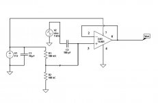
The circuit has to be run off a 9v battery and also requires a high input impedance.
I'm using an op amp for the impedance buffer, so have created Vcc/2 for virtual ground.
The problem is that the DC operating point is not right at the +input of the op amp - it's at c.0.95V from a supply of 8.72V and VRef of 4.15V. I have attached the circuit. All other points are working at the DC op point I expected.
I'm almost 100% sure that this problem is something to do with the high value of R3. I have altered the values for R1 and R2 to compensate for the value of R3 and can get a bit closer to Vcc/2 but in order to get there properly I would need to increase R1 / R2 by a lot. This is a problem, especially as this is an audio circuit, in terms of Johnson noise contribution it would make.
So, I was wondering if anyone had any ideas on how to get around this?
I was thinking about using a rail splitter op amp like the TLE2426, but I don't know if this would make any difference when faced by such a high R3 value. I have already tried buffering the voltage divider and that didn't help...
Any thoughts much appreciated.
Thanks
I'm struggling with a biasing arrangement for an audio preamp I'm building.
The circuit has to be run off a 9v battery and also requires a high input impedance.
I'm using an op amp for the impedance buffer, so have created Vcc/2 for virtual ground.
The problem is that the DC operating point is not right at the +input of the op amp - it's at c.0.95V from a supply of 8.72V and VRef of 4.15V. I have attached the circuit. All other points are working at the DC op point I expected.
I'm almost 100% sure that this problem is something to do with the high value of R3. I have altered the values for R1 and R2 to compensate for the value of R3 and can get a bit closer to Vcc/2 but in order to get there properly I would need to increase R1 / R2 by a lot. This is a problem, especially as this is an audio circuit, in terms of Johnson noise contribution it would make.
So, I was wondering if anyone had any ideas on how to get around this?
I was thinking about using a rail splitter op amp like the TLE2426, but I don't know if this would make any difference when faced by such a high R3 value. I have already tried buffering the voltage divider and that didn't help...
Any thoughts much appreciated.
Thanks
Attachments
Try this. The input impedance is around 50K (that's not high ") ) and is the value of R1 and R2 in parallel.
) and is the value of R1 and R2 in parallel.
You can go as high as you want with R1 and R2. Even up to 10 Meg ohms or even far higher still if you can guarantee no external leakage or conduction paths.
C3 could usefully be lower in value, particularly if you use higher value resistors. Make sure you have the polarity correct.
Pin 3 has to be at one half Vcc using equal value resistors. If it is not the opamp is faulty or incorrectly wired. However... remember your meter loads the circuit too and if its a low ohms/volt type then that would pull the apparent voltage down on those resistors. If the opamp output is at 4.5 volts then pin 3 should be at an identical voltage too.
Don't worry over noise at this stage. And remember you probably need a cap at the output too.
) and is the value of R1 and R2 in parallel.You can go as high as you want with R1 and R2. Even up to 10 Meg ohms or even far higher still if you can guarantee no external leakage or conduction paths.
C3 could usefully be lower in value, particularly if you use higher value resistors. Make sure you have the polarity correct.
Pin 3 has to be at one half Vcc using equal value resistors. If it is not the opamp is faulty or incorrectly wired. However... remember your meter loads the circuit too and if its a low ohms/volt type then that would pull the apparent voltage down on those resistors. If the opamp output is at 4.5 volts then pin 3 should be at an identical voltage too.
Don't worry over noise at this stage. And remember you probably need a cap at the output too.
Attachments
Thanks for the replies everyone. The R3 100 ohm value was a mistake - it should have been 10 Meg ohms! I was messing around with the simulator and forgot to change the value back before posting - schoolboy error...
The problem did indeed turn out to be the multimeter I was using pulling the voltage down - I connected an LED at op amp Vout and probed the +Vin of op amp and the LED went out...
Turns out there is nothing wrong with the circuit.
The input coupling cap will be smaller in the final version - just put it in there as that value for the time being. Will also add an output cap as well.
Thanks again guys.
- Status
- This old topic is closed. If you want to reopen this topic, contact a moderator using the "Report Post" button.