Work? Probably. Good way to do it? Probably not.
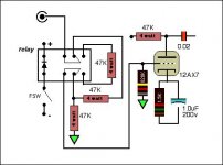
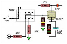
Look at your circuit. IN one state (as shown) you have a 47k resistor in series with the input signal with another 47k to ground (parallel with the 820k grid resistor). In the other state, you have a 47k in series with the input signal, but no extra resistor to ground. Since ther is a 47k in series either way, why have two and switch them? Your circuit boils down to the relay putting a 47k in parallel with the 820k or not. SO we can elimiate those extra relay contacts, just have one SPST set of contacts enabling that parallel resistor when wanted.
That was the doing it part. Now the other part. It is generally not a good idea to do much with the signal until it has gone through at least the first tube stage. It gets the signal up away from the noise floor. What you are proposing is not unlike the simple voltage divider Fender used on a million amps, but they just wired two input jackis to make the change. Adding relays and stuff is just asking for noise and pops.
Did you get a spefcial deal on giant 47k power resistors or something?
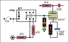
Yes I got a deal on those 4 watters.
This setup is the same as most Fenders and Marshalls that have two separate inputs, high and low. All I am doing is switching between the two. And here is a better drawing that does not put the 47K to ground in parallel with the 820K
This setup is the same as most Fenders and Marshalls that have two separate inputs, high and low. All I am doing is switching between the two. And here is a better drawing that does not put the 47K to ground in parallel with the 820K
Attachments
That answers my concerns, but now all you are doing is changing the series from 47k to 94k. I don't think that is what you intended.
The way the typical Fender works, is in the high gain jack, your two 68k resistors wind up in paralle, and the resulting 34k resistance is in series with the input signal. Plugging into the low gain jack, puts the two 68k in series, one end at the inpit, the other end at ground, and the center junction is the signal feed into the amp. That is a 1/2 voltage divider, and drops the signal voltage to 1/2.
I think that is what you are trying to do, and rally, changing the total resistance of the 820k is one way to go about it. Try this, wire one of your 47k in series - that is from jack to grid. Then try tacking or just clipping some different resistors across the 820k, just to see how it reacts. In fact you could remove the 820k and tack in something like a 1 meg trim pot wired as a variable rsistor. The turn it up and down to see how it affe3cts the stage. That would let you come up with some different resistances that would alter your voltage divider. Note what settings of the trimmer seems to give you the two levels, meaure the trimmer at each setting, then we find resistors close to those values.
Thanks Enzo, I found some more info on how the high/low jacks work. For the typical Fender, on high input, the 68K and 1M make a divider but not hardly any cut, pretty much all of the signal. Then in the low input the 1M is grounded out and you are left with two 68K's dividing the input in half. So my set up would need to be a little different and the 820K and 47K in parallel would give a little less than 47K combined with the other 47K as the shunt. I would probably raise the load resistor to find the amount of cut I want because half will be too much I think.
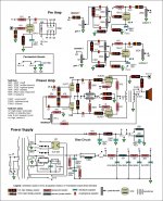
Here is the amp I built: I would then change the 820K resistors on the pots-they tame the gain-so I have a nice switchable gain without getting unstable.
Here is the amp I built: I would then change the 820K resistors on the pots-they tame the gain-so I have a nice switchable gain without getting unstable.
Attachments
- Status
- This old topic is closed. If you want to reopen this topic, contact a moderator using the "Report Post" button.