Hi,
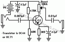
I'm building a rangemaster clone pedal (baby steps in diy audio) and have been trying to understand how it all works. I think I get most of it, but am not quite sure what the deal is with the 47uF capacitors. Do they smooth out any ripple from the battery (isn't a battery output pretty smooth), or do they act like a reservoir to assist in quickly supplying changing current loads across the battery? Surely current draw is not enough to cause much of a voltage drop.
Finally, and most importantly, what is special about 47uF? can different capacitances be used? will they make any difference to the sound? are they necessary at all?
Thanks
Nick
May I suggest you post or link to a schematic so we know just what you are referring to?
A "filter" cap across the battery serves to decouple the circuit from the battery - prevents the battery from interacting with the signal.
The value of such a cap is not critical. 47uf would be eneough, 100uf would be fine, and 22uf probably as well.
Such a cap would also serve to filter under-filtered wall wart power if your pedal has a wall wart jack.
May I suggest you post or link to a schematic so we know just what you are referring to?
I've attached one from this thread.
A "filter" cap across the battery serves to decouple the circuit from the battery - prevents the battery from interacting with the signal.
Ah, I will google. Decoupling seems to be the key word (I'm something of a noob and couldn't find what I was looking for searching battery filter caps.)
The value of such a cap is not critical. 47uf would be eneough, 100uf would be fine, and 22uf probably as well.
But something in that range, not 100nf for example?
Attachments
Ah, I see. The other 47uf is a emitter bypass cap, and it affects the gain and frequency response of that single amplifier stage. You might even experiment with a 22uf or 10uf there. IN fact, try leaving it out to see how that sounds, just to learn.
I found a version of this over at RG's Geofex site. I suggest you visit there, and look on the left side menu near the top for two things: Circuit Sweepings and FX projects. The web site has tons of great information for you. The FX project is based on the Rangemaster, read through it. In the Sweepings is an article titled "what are all those parts for?" Read that too.
New Page 1
Ah, I see. The other 47uf is a emitter bypass cap, and it affects the gain and frequency response of that single amplifier stage. You might even experiment with a 22uf or 10uf there. IN fact, try leaving it out to see how that sounds, just to learn.
I found a version of this over at RG's Geofex site. I suggest you visit there, and look on the left side menu near the top for two things: Circuit Sweepings and FX projects. The web site has tons of great information for you. The FX project is based on the Rangemaster, read through it. In the Sweepings is an article titled "what are all those parts for?" Read that too.
I'm reading the "what are all those parts for" article now.
Thanks for the info.
- Status
- This old topic is closed. If you want to reopen this topic, contact a moderator using the "Report Post" button.
