hey
yes, the square one is on the wrong side - should have clarified that!
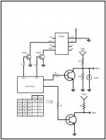
i was thinking that leaving the other inputs of the NJM2521 empty, i could switch between my input signal and "nothing" - thus muting the channel. does that make sense?
i might need to clarify the project a little further.
this PCB is a part of a musical instrument, where each channel is one note, controlled by a keyboard. there will be 12 stereo amp chips, giving me 24 notes to play with.
thats why i need to be able to turn the channels on/off very rapidly, through a digital interface (the arduino)!
updated pcb with ground fill ::

thank you for all your help!
yes, the square one is on the wrong side - should have clarified that!
i was thinking that leaving the other inputs of the NJM2521 empty, i could switch between my input signal and "nothing" - thus muting the channel. does that make sense?
i might need to clarify the project a little further.
this PCB is a part of a musical instrument, where each channel is one note, controlled by a keyboard. there will be 12 stereo amp chips, giving me 24 notes to play with.
thats why i need to be able to turn the channels on/off very rapidly, through a digital interface (the arduino)!
updated pcb with ground fill ::
thank you for all your help!
this PCB is a part of a musical instrument, where each channel is one note, controlled by a keyboard. there will be 12 stereo amp chips, giving me 24 notes to play with.
This is a crazy way to make an instrument. You can't connect the amplifier outputs together (to one speaker), or readily mix them, so you're going to need 24 speakers.
Generate your tones, feed them to the keyboard, send the output of each key to the same amplifier. You can use a mixer (opamp summer) in front of the amplifier.
If the keyboard has all the keys connected together on one side, then use the outputs to switch the tones to the summer (using logic level controlled analog switches, for example, or jfets), or simply use the keyboard to switch the tone generators on and off.
Draw a diagram of the keyboard, or post a link to a datasheet for it, or at least show where it comes from, or tell us how it is connected.
Draw a diagram or provide some information on how you intend to generate the tones.
the instrument i am making is actually a harp. i have 24 coils connected to each channel. the solenoids drive 24 strings by a feedback loop (the input is a piezo pickup, on the bridge - through a preamp)
i have made a similar instrument before, seen here :: ulfurhansson.com.
this PCB is part of v2.0 of the instrument.
that being said, could you provide your thoughts on this PCB?
sorry for being so vague!
best,
ú
I do not think so because the "thump" come from the rails voltage coming down. If one dropped faster than the other this will unbalance the output drivers and consequently generating the "thump". This is my opinion that cause the "thump". Still you can ground the input too you do not loose anything. The mute in my LM3886 worked perfectly. You do not heard anything in the speaker.
OK, I looked at your site, I think I understand why you want 24 amplifiers.
It's hard to comment on the design without knowing a bit more detail about how it works. I have some experience of capacitive touch switching, I used PIC microprocessors to read the pads.
I am a guitarist, I played several different instruments in the past.
Give me some time to think about what you are doing, I will help you.
As far as the PCB is concerned, I think that leaving some of the inputs of the NJM2521 'empty' will work, but I would put a small value resistor (100R) to ground, rather than leaving them 'floating' as this might result in unwanted noise. I also think that the NJM2521 is probably not the best way to spend your money. I found some on ebay, but they cost ~U$5. I think we could find a better, smaller, cheaper solution.
You need to make your PCB drawing in the standard form. Components on the top nearest the viewer, PCB, solder side tracks furthest away. That is how everybody does it, it will be easiest for people to understand if you follow the standard. I will post a drawing so that you see clearly what I mean.
Have you thought about heatsinks and what kind of box you will put the electronics in? Or do they go inside the instrument itself? It's often best to put chips like the LM1876 at the edge of the board, so that it can be screwed to the case, maybe with a heatsink on the other side of the box wall. I like to think about things like this from the beginning, and design the PCB to fit.
OK, I looked at your site, I think I understand why you want 24 amplifiers.
It's hard to comment on the design without knowing a bit more detail about how it works. I have some experience of capacitive touch switching, I used PIC microprocessors to read the pads.
I am a guitarist, I played several different instruments in the past.
Give me some time to think about what you are doing, I will help you.
As far as the PCB is concerned, I think that leaving some of the inputs of the NJM2521 'empty' will work, but I would put a small value resistor (100R) to ground, rather than leaving them 'floating' as this might result in unwanted noise. I also think that the NJM2521 is probably not the best way to spend your money. I found some on ebay, but they cost ~U$5. I think we could find a better, smaller, cheaper solution.
You need to make your PCB drawing in the standard form. Components on the top nearest the viewer, PCB, solder side tracks furthest away. That is how everybody does it, it will be easiest for people to understand if you follow the standard. I will post a drawing so that you see clearly what I mean.
Have you thought about heatsinks and what kind of box you will put the electronics in? Or do they go inside the instrument itself? It's often best to put chips like the LM1876 at the edge of the board, so that it can be screwed to the case, maybe with a heatsink on the other side of the box wall. I like to think about things like this from the beginning, and design the PCB to fit.
hey, great - im eager to hear your further thoughts.
unfortunately i already ordered a batch of the NJM2521! im sure they will work fine, even though i end up with a "shooting a mosquito with a shotgun" situation.
good call on adding resistors to the empty inputs of the NJM2521. i will definitely add them to the PCB.
i put the back of the LM1876 towards the rim so i could heatsink the array properly. i will probably use a copper "ring" or wheel for heatsinking, so i can use it to mount the circuits inside the instrument (which will be circular, much like the earlier prototype on my website).

earlier prototype from last year - casing will be similar this time
i based the PCB im making on the one found here ::LM1876 project
i made a working amp using this website and it works GREAT on my piano. so, amp circuit should be fine, still - maybe you have some extra tips.
im working on the fritzing PCB file as we speak. here is a neater version, with component labels (keep in mind that there are two sides, the one with most components is mirrored :

and finally, here is a video of an earlier prototype using LM386's - just to see/hear what im going for (this version uses electromagnetic pickups for each string - im aiming for a single piezo this time) :: https://vimeo.com/32643008
i'd love to know what you think!
and if you have any further questions to clear things up, please ask.
thanks again,
úlfur
hmmm.... wondering if i wanted the arduino pin HIGH signal to unmute the audio, wouldn't it make sense to connect the audio input signal to pin 3 of the NJM2521, rather than pin1?
that way an arduino LOW signal would mute the inpute, HIGH would let it flow through... amirite?
that way an arduino LOW signal would mute the inpute, HIGH would let it flow through... amirite?

I didn't read back through the thread, so sorry if I missed something. But looking at your drawing, I see you are using input #2. And the logic for selecting input 2 involves SW1 being logic HI and SW2 being logic LOW. Your drawing shows no connection at all to SW2. Connect SW2 to ground, and then bringing SW1 hi with your module ought to select input 2 to the output.
- Status
- This old topic is closed. If you want to reopen this topic, contact a moderator using the "Report Post" button.
- Home
- Live Sound
- Instruments and Amps
- LM1876 arduino mute