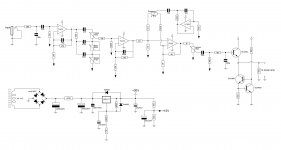
I am starting this thread to discuss a problem that occurred after constructing the guitar preamp shown in the schematic attached.
The preamp is fed into a transistor power amp - a JLH 30 watt design. It works pretty well, and is designed to have sufficient headroom for input voltages up to 1 Vpp.
The strange thing that happens (I posted it on another thread, but could not provide sufficient information) is that when turning on the amp, I can hear a subtle "charging" noise of several kHz, that lasts for some seconds and then goes. I say "charging", because it is clearly pretty much like such a sound.
I assume that an oscillation happens before the power supply is stabilised. I have made the following tests:
Does anyone have a similar experience or solution in mind? Thanks in advance!
The preamp is fed into a transistor power amp - a JLH 30 watt design. It works pretty well, and is designed to have sufficient headroom for input voltages up to 1 Vpp.
The strange thing that happens (I posted it on another thread, but could not provide sufficient information) is that when turning on the amp, I can hear a subtle "charging" noise of several kHz, that lasts for some seconds and then goes. I say "charging", because it is clearly pretty much like such a sound.
I assume that an oscillation happens before the power supply is stabilised. I have made the following tests:
- applied a 2.2R resistor in series with a 2.2uF tantalum cap across the +30V terminals - nothing happened
- turned all controls down - no change in the noise
- discarded the 220u cap - the noise became louder but shorter
- removed both the 220u and the LM317 supply, feeding the preamp through a 1k resistor connecting on the 1000u cap - same results as before
- short-circuited the power amp's input - no such noise could be heard, which persuaded me it came from the preamp
- simply removed the LF353 IC from its socket, without making other changes - no noise
Does anyone have a similar experience or solution in mind? Thanks in advance!
Attachments
Last edited:
I don't have much of a clue what the problem is, but after a little thought, a simple way to make sure the +15V voltage goes up proportionally with the +30V voltage is remove the 22u at the +30V output and put it across the top 100k divider resistor, and put an identical value across the bottom 100k resistor (of course removing the 220uF there). If you need about 22u across the regulator output, use two 47u's across the divider resistors.
the inputs to the opamps are outisde of the common mode range for a long time during turn-on. For the opamp to do what you expect, its inputs (both TL072 and LF353), per the data sheet, must be at least 3 volts above the negative rail.
The previous poster's suggestion would make that happen more quickly.
In the worst case, you might need some kind of mute circuit.
There are also some other ways to make the "+15V" rise more quickly.
Akitika GT-101
Update My Dynaco
The previous poster's suggestion would make that happen more quickly.
In the worst case, you might need some kind of mute circuit.
There are also some other ways to make the "+15V" rise more quickly.
Akitika GT-101
Update My Dynaco
the inputs to the opamps are outisde of the common mode range for a long time during turn-on. For the opamp to do what you expect, its inputs (both TL072 and LF353), per the data sheet, must be at least 3 volts above the negative rail.
The previous poster's suggestion would make that happen more quickly.
In the worst case, you might need some kind of mute circuit.
There are also some other ways to make the "+15V" rise more quickly.
Akitika GT-101
Update My Dynaco
Well, thanks for both answers! It seems to be a logical explanation that the behaviour becomes unpredictable until the 3V are reached, but I tried the instant rise by removing the 220u, and the situation changed, but not the way I wanted (see my first post). I will give it a try and have a look at the sites you posted too, when I find time.
Still it is weird, but the parallel rise in the supply rails should be given a chance!
another more complicated way would be to have separate positive and negative regulators, then the "15V" point which is your supply midpoint would just be the center tap of the transformer.
Of course! However, the goal of this design was to build something out of existing parts (bulky transformer with no centre tap), that would be extremely simple and small.
In this manner, I am well aware of the fact that this design is not even close to a thoroughly planned hi-fi scheme - but it works and is very cheap.
Well, it works with this little exception.

Last edited:
The strange thing that happens (I posted it on another thread, but could not provide sufficient information) is that when turning on the amp, I can hear a subtle "charging" noise of several kHz, that lasts for some seconds and then goes. I say "charging", because it is clearly pretty much like such a sound.
I assume that an oscillation happens before the power supply is stabilised.!
Does it really matter if you just want a cheap solution ?
Its not as if you are selling it as pro equipment.
Does it really matter if you just want a cheap solution ?
Its not as if you are selling it as pro equipment.
Well, you are right in a way. But after all, I don't think it is right to know that your circuit tends to oscillate even in such a way. Because that could be bad for the components used - if I don't know the cause, how can I be sure that it won't stress my speaker, or burn any transistors? It could also be oscillating in much higher frequencies that are not audible.
So, why preserve a possibility of damage? Even if the equipment is not that serious.
Plus - and that could demystify my approach - it is my first amp build, and I want to do it the right way from all aspects in order to lay the foundation for future proper designs and gain precious experience.
So, why preserve a possibility of damage? Even if the equipment is not that serious.
.
It wont damage the amplifier.
Unless you have put less wattage speakers than the amplifier it wont damage your speakers either.
Well, thanks for both answers! It seems to be a logical explanation that the behaviour becomes unpredictable until the 3V are reached, but I tried the instant rise by removing the 220u, and the situation changed, but not the way I wanted (see my first post).
I'm thinking the noise became louder because there was plenty of feedback through the unbypassed "ground" connection.discarded the 220u cap - the noise became louder but shorter
Looking again, it still happened because the 470 ohm and 1,000uF in the power supply slow down the power supply rise time substantially, to a large fraction of a second. Short out that resistor, and toss out the 1,000uF as well. The regulator will reject the ripple voltage very well on its own, and there's not much current (thus not much ripple voltage) in this circuit to begin with.
Trying to respond to everyone:
jaycee: I have already responded to that! I was meant to make an extremely simple design that could simply work - not build a superior amp. I don't mean this regular supply you suggest is rocket science, but was rejected for personal reasons, if you wish! Thus, you have the right to completely disagree. But I don't think it is immediately visible that it could have that flaw - even though it seems annoying as a scheme. I posted it again: the build was mainly for educational purpose. Now I think I have learned I should always seek for symmetrical supplies. In the real world, though.
nigelwright7557: I think you are not mistaken, but seems like I did not put it exactly the way I wanted: I want to learn how to build things the right way. Even if it won't matter sometimes - there will be an occasion that it could matter.
benb: I see what you mean, and it seems logical. By the way, there is more current drawn from the 2200u, since it is there where I connect the power supply of the power amp - yet, you could not know that! Even though it may cause negligible ripple too. But I will try this amendment, and should it cure the problem maybe try a shorter time constant!
Soon I will be able to play with it again.
I guess I didn't phrase my post very well... sorry.
You might get quicker startup by replacing the two resistors/capacitor with a 7815 regulator. You should be able to retrofit it to an existing layout too.
There are a couple of alternatives - one is a symmetric supply. All this really requires is a transformer with either dual secondaries, or a centre tapped transformer. You can even make it with a single secondary, using half wave rectification which is good enough for a few opamps. Often you can get a plugpack supply with an AC output and use that.
Another is a virtual ground - this is similar to what you are doing, but usually with an active source such as a regular, or an opamp to create VCC/2.
I guess I didn't phrase my post very well... sorry.
You might get quicker startup by replacing the two resistors/capacitor with a 7815 regulator. You should be able to retrofit it to an existing layout too.
There are a couple of alternatives - one is a symmetric supply. All this really requires is a transformer with either dual secondaries, or a centre tapped transformer. You can even make it with a single secondary, using half wave rectification which is good enough for a few opamps. Often you can get a plugpack supply with an AC output and use that.
Another is a virtual ground - this is similar to what you are doing, but usually with an active source such as a regular, or an opamp to create VCC/2.
Well, using an opamp to deliver VCC/2 was my initial thought to be honest! Just discarded the option out of laziness of putting another IC on the layout.
I am also considering the 7815 regulator. Thanks for the advice! I hope I will have syfficient room, as you say.
Tried the regulator solution, and it seems to be working flawlessly.
I discarded the 2x100k, 220u network and replaced them with a 78L15 regulator, putting in series with its input a 1k8 resistor to drop the voltage. I added 10u at the 15 volt stabilised output, in parallel with a 4k7 resistor to draw some current. Eventually it will not be needed, since about 2,5-3 milliamperes are already drawn.
So, no "charging noise"! I did receive a second pop on turn-up, coming from the preamp - sharper than the pop coming from the output stage, which is smoother. I removed the LF353 from the circuit to check it came from the preamp's new supply and was not a remaining of the old problem, and it was still there.
So, problem fixed for the time being! I am going to try fitting a soft starter to get rid of these pops. By the way, I am leaning towards using a simple soft starter published in Elektror Electronics - using a bridge and RC networks.
Many thanks for all of your answers!
a soft starter?
A soft starter dulls just the enormous inrush current for a few 100 milliseconds - It is meant to protect the transformer, switch and fuse from the first extreme peak start-up current. This usually doesn't stop clicks and pops when the rail voltages eventually rise and amplifiers begin to settle - when thumps and pops occur.
You use a muting circuit to kill the input to the amplifier at turn-on for what you require. Domestic amplifiers use the speaker relay for the same purpose.
I am aware of that and these uses - speaking of the soft starter. I just supposed this would help, because in the first place, when the 15 volt rail was slowly raised, no such pop existed.
Anyway, I just want to experiment a bit. Speaking of muting circuits, by the way, I don't know anything at all. Could you point me towards a simple circuit used for muting? Based on your experience.
Thanks for the input!
The popping thats left will be from signal coupling capacitors charging. This is another reason why a symmetric supply is preferred - just so you know
A muting circuit can be as simple as a time delay of some kind (an R-C delay, or even a 555 timer) which will eg engage a relay to connect the signal after a short time delay. This allows the circuit time to stabilise
A muting circuit can be as simple as a time delay of some kind (an R-C delay, or even a 555 timer) which will eg engage a relay to connect the signal after a short time delay. This allows the circuit time to stabilise
- Status
- This old topic is closed. If you want to reopen this topic, contact a moderator using the "Report Post" button.
- Home
- Live Sound
- Instruments and Amps
- Odd "charging" noise in guitar preamp