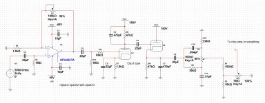
Yeah, I was going to build the real mctube guitar pedal. Then I thought well what if I integrated a tube screamer clone into it. then I found the schematics for an orange tube head so I took the 3rd gain stage and part of the "phase inverter"(I think that's what they call it) then dropped a high voltage op-amp in-front to makeup for the first two gain stages. Not exactly design work but its not a perfect clone either. To answer your question.... yes I plan on putting a high gain metal petal in-front of my mutant preamp. I'm note sure how everything will pan out but it looks promising.
The op amp, as is, is less amplification than a single 12AX7 or similar gain stage.Yeah, I was going to build the real mctube guitar pedal. Then I thought well what if I integrated a tube screamer clone into it. then I found the schematics for an orange tube head so I took the 3rd gain stage and part of the "phase inverter"(I think that's what they call it) then dropped a high voltage op-amp in-front to makeup for the first two gain stages. Not exactly design work but its not a perfect clone either. To answer your question.... yes I plan on putting a high gain metal petal in-front of my mutant preamp. I'm note sure how everything will pan out but it looks promising.
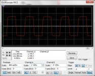
You could probably increase it more without it clipping, depending on which pedal you put into it, (you don't want to clip the op amp). A Tube Screamer gives out about 1 volt peak-to-peak, and the op-amp can probably handle 70 volts peak-to-peak before clipping. Not sure how much gain the OPA453 can take and stay stable, but you could try dropping R5 by degrees down to about 1K5 for maximum gain.
Of course, for a higher gain pedal it will probably be fine as configured. In fact if your pedal is giving out really high signal, like 7V peak-peak (pretty much the most possible from a 9V battery) then you might want to keep R5 as it is and lower R6.
Your absolutely right, I swapped the feed back resistor on the opamp for a 100k pot changed R5 to 1.2k, removed all other pots except for R21. and I'm thinking about changing the anode resistors on the tubes, but I'm not exactly sure how to go about doing that. I was skimming through that book recommendation ya sent me. From what I read your suppose to choose a val for the anode resistor then consult the chart for the current then use that information to calc the cathode resistor.... right? If this is the case then at 150 volts with an anode resistance of 47k biased at 1 volt my cathode resistance should be 15k. but for some reason I still think I'm missing something here. I'm looking forward to your response.
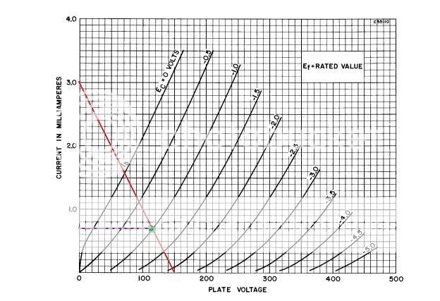
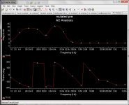
This is the load line for 47K as 150/47K equals 3mA near as damn. Notice how you will get less swing of plate voltage as the line is steep. So 47K means less gain than 100k.
At 1V grid you get 0.7mA. 1V/0.7mA gives about 1K5, so I think you missed a decimal point somewhere.
You can play around with biasing by biasing hot (more mA, less grid voltage, so smaller cathode resistor) or cold (the opposite) to change the clipping characteristics. Basically, as the signal swings the grid voltage around it will do different things when it moves up and to the left on the load line as when it moves down and to the right. I've heard said the former is a harder clip, and the latter a softer compression, but I'm not sure this is right, as when you move toward 0V bias grid leak starts affecting biasing, which, to my ears, softens the clipping too.
A 10K trimmer on the cathodes is a good plan. Or a log pot (log is a better taper here). Just remember to turn off and bleed the caps before you poke around with a screwdriver. The second triode has a lot of volts at the cathode, and even though the first one doesn't, you could slip.
The bias at the second triode will make a bigger difference to the sound, by the way.
(Also, this load line is not so great an approximation AC effects like gain, and clipping, as you have to factor in the AC load, which includes all that comes after the anode. You can pretty easily draw an AC load line though)
Last edited:
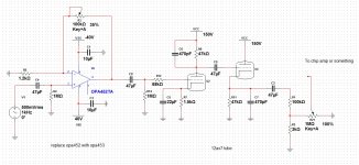
You've changed second triode to an AC coupled cathode follower. You'll get no voltage gain out of it. You've also missed out the grid leak resistor (which also biases the grid) and the cathode bias resistor.I added a simple tone control, but I think I will leave it out.
Also, the high cathode voltage means you'll probably have to elevate the heater.
Last edited:
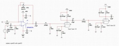
I don't think you'll be happy with what you've done there. Rk of 39k will give you a fuzzy (almost fluffy) compressed sound with no headroom. If you're looking for a good wide range of overdrive I think you should go with a DC coupled cathode follower. Read this, all of it. DC Coupled Cathode Follower
You will want to have an output level control. Take a look at the bottom of the AC Cathode follower page and you'll see an example for an effects loop. The send level control is what you want to do. It's simple and doesn't affect the tone.
Also, have you decided what to do with your heater voltage? If you don't have 12.6V anywhere you might want to regulate down from your 40V supply and have a nice, stable 12.6V DC heater. With only 1 tube the load will only be 150mA.
Also, have you decided what to do with your heater voltage? If you don't have 12.6V anywhere you might want to regulate down from your 40V supply and have a nice, stable 12.6V DC heater. With only 1 tube the load will only be 150mA.
")
- Status
- This old topic is closed. If you want to reopen this topic, contact a moderator using the "Report Post" button.
- Home
- Live Sound
- Instruments and Amps
- Hybrid amp design