I installed the insulators as instructed and hooked the power and the current limiter lit but just barely.
Between Quote 1 and Quote 2 I don't see: "I measured all voltages and found them normal".So I hooked directly to power and flipped the switch
Sorry, I understand your anxiety, but please let's slow down a bit, we are real close anyway.
I've just arrived to my shop after travelling all over the city buying parts (such as nails/glue/speaker cloth/tapestry staples/paint) so *now* I won't be suggesting an answer, but stay tuned that late at night or tomorrow morning I'll suggest some tests.
But rest assured that we are close.
Good luck.
Fine.
I understand you pulled the TIP screws, added the nipples and re mounted them.
The big question is: measure again from collectors (center legs ) to ground, do you still have those shorts you measured before?
I guess not, but measuring beats guessing big time.
If not, turn amp on, please measure +/-V rails and DC voltage at the speaker output.
I expect normal (say +/- 30 to 40V rails, less than 100mV DC at speaker out) .
If so, measure bias voltage , from Q18 to Q19 base (left pin of TIP31/32) I expect around 2.5V DC or current, measure voltage from Q20 to Q21 emitters (right pin), I expect around 10mV DC.
Thanks.
PS: still always with the bulb limiter.
I did check the collectors. None of them are shorted now. I did that as soon as I added the insulators. THEN I used the current limiter. THEN I tried it without the current limiter. I didn't get the speaker measurement, sorry about that. I will get that for you.
"measure bias voltage , from Q18 to Q19 base (left pin of TIP31/32) I expect around 2.5V DC or current, measure voltage from Q20 to Q21 emitters (right pin), I expect around 10mV DC.
Thanks"
I know where you are telling me to place the red lead but where am I hooking the black lead for these tests?
Thanks!
BR
"I know where you are telling me to place the red lead but where am I hooking the black lead for these tests?"
He asked for the voltage between the bases of Q18 and Q19. (the left leg of each) SO you put your red lead on one,and the black lead on the other.
We are measuring the voltage from one to the other.
Think of a shelf on your wall. We could ask how high it is above the floor. That would be like the voltage to ground. Or we could ask how long the shelf is - the distance end to end. The distance from one end to the other. It wouldn;t matter how high off the floor it was, we wanted the length. I hope that analogy is not confusing.
Enzo
Enzo
Thanks for clarifying things for me.
I wasn't having a problem differentiating between the two different tasks he presented me with. I was having a problem with the procedures of accomplishing them. I am learning the lingo and the associated procedures but I still have a ways to go, but I will get there with help from folks like yourself. Thanks!
BR
He asked for the voltage between the bases of Q18 and Q19. (the left leg of each) SO you put your red lead on one,and the black lead on the other.
We are measuring the voltage from one to the other.
Think of a shelf on your wall. We could ask how high it is above the floor. That would be like the voltage to ground. Or we could ask how long the shelf is - the distance end to end. The distance from one end to the other. It wouldn;t matter how high off the floor it was, we wanted the length. I hope that analogy is not confusing.[/QUOTE]
If u can buy a crystal phone(the high impedance earphone), u can find the faulty stage and don't have to look around the total amp, for the fault.
Gajanan Phadte
If you are going to offer a suggestion like this it would help if you explained how to make use of the info. Thanks!
BR
Amp unplugged, Collector to ground:
Meter Setting Diode Q20 = 1.516 / Q18 = 1.503 / Q19 = .489 / Q21 = .488
Meter set to ohms: Q20 = 4.01 / Q18 = 4.6 / Q19 = 2.02 / Q21 = 1.83
Amp plugged in through current limiter:
Q18 to Q19 base pin bias (left pin to left pin) = 1.65V DC
Q20 to Q21 Emitters (right pin to right pin) = 110.5mV DC
No Speaker connected: P1 to P2 = 9.2 mV DC
P3 to P4 = 023 VDC
P3 to P5 = 1.45
P4 to P5 = .45
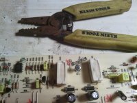
On the schematic TP3 is (+42 rail) TP4 is (-42 rail) I cannot locate either terminal on the PCB. However the schematic shows R144 and R145 to be connected to both rails. I am not sure which side of each resistor is + or - See pic - Touching the end of each resistor on the side towards the strippers shows 63VDC The side closest shows 31.45VDC
Just figured this out.
The collector legs of Q21 and Q19 are on the -42 rail = 32.84VDC
The collector legs of Q18 and Q20 are on the +42 rail. = 32.64VDC
As a side note, when I touched the test lead to to R144 (left) its loose. The metal leads seem to be ok but the body moves easily. I checked the ohm (amp unplugged) of R144 (top side) and get 340 ohms. When I flip the PCB over and test the terminals at the solder joints, I get an open. R145 show 340 on top and bottom.
I haven't done anything yet and won't until I get instructions from you. I think the joints need to be desoldered and resoldered.
I await your instructions.
BR
Meter Setting Diode Q20 = 1.516 / Q18 = 1.503 / Q19 = .489 / Q21 = .488
Meter set to ohms: Q20 = 4.01 / Q18 = 4.6 / Q19 = 2.02 / Q21 = 1.83
Amp plugged in through current limiter:
Q18 to Q19 base pin bias (left pin to left pin) = 1.65V DC
Q20 to Q21 Emitters (right pin to right pin) = 110.5mV DC
No Speaker connected: P1 to P2 = 9.2 mV DC
P3 to P4 = 023 VDC
P3 to P5 = 1.45
P4 to P5 = .45
On the schematic TP3 is (+42 rail) TP4 is (-42 rail) I cannot locate either terminal on the PCB. However the schematic shows R144 and R145 to be connected to both rails. I am not sure which side of each resistor is + or - See pic - Touching the end of each resistor on the side towards the strippers shows 63VDC The side closest shows 31.45VDC
Just figured this out.
The collector legs of Q21 and Q19 are on the -42 rail = 32.84VDC
The collector legs of Q18 and Q20 are on the +42 rail. = 32.64VDC
As a side note, when I touched the test lead to to R144 (left) its loose. The metal leads seem to be ok but the body moves easily. I checked the ohm (amp unplugged) of R144 (top side) and get 340 ohms. When I flip the PCB over and test the terminals at the solder joints, I get an open. R145 show 340 on top and bottom.
I haven't done anything yet and won't until I get instructions from you. I think the joints need to be desoldered and resoldered.
I await your instructions.
BR
Fine.
I understand you pulled the TIP screws, added the nipples and re mounted them.
The big question is: measure again from collectors (center legs ) to ground, do you still have those shorts you measured before?
I guess not, but measuring beats guessing big time.
If not, turn amp on, please measure +/-V rails and DC voltage at the speaker output.
I expect normal (say +/- 30 to 40V rails, less than 100mV DC at speaker out) .
If so, measure bias voltage , from Q18 to Q19 base (left pin of TIP31/32) I expect around 2.5V DC or current, measure voltage from Q20 to Q21 emitters (right pin), I expect around 10mV DC.
Thanks.
PS: still always with the bulb limiter.
Attachments
Power Rails
I've been reading about amplifier circuits and studying my schematic. I am learning about power rails and the common or GNDA.
R144 is on the + rail and shows 30VDC before and 15 VDC after
R145 is on the - rail and shows basically the same readings.
Both of these resistors show 340 ohms (connected to the circuit) The schematic shows these to be 200 ohms with 10% tolerance. 200 + 10% is 240 ohms so at first glance, these are way too high. Of course they are hooked to the circuit so something else may be influencing the reading.
I need to correct the results I gave yesterday for p3 and p4. There is actually 26 volts AC on each. I was under the impression these points are DC but these are the connections where the AC has been stepped down but before the diodes where one side of the AC wave is filtered out (or blocked) to provide a half ripple and then through the 4700uf caps which charge and "slowly" discharge (at a slower rate than the rectified half ripples) which gives us a smooth or "clean" DC supply of power.
I gotta tell you I was thinking the transformer had taken a crap. What was throwing me off was that I had dc power down stream of the caps. But anyway...
So... So far I have (I believe) the correct or close to correct voltage where its supposed to be. So I am at a loss as to why the amp isn't producing sound when I plug the guitar in.
More reading and studying...
BR
Attachments
Last edited:
A whole circuit dead
I've been comparing the schematic and voltages that should be present.
If you look on the schematic in the lower right hand corner you should find D38 and D39. On the banded end of each diode I have line voltage. D38 is + 30v and D39 is -30v But the two connections between them, the top one leads to the positive speaker terminal, is all dead. From there all the way across the page (going left) the whole circuit is dead. R77 and 78 have no power. I cannot seem to locate R79. I can find everything else but that one is hidden apparently. This whole area ties into U6-A and B I can't seem to figure out the common denominator here but this is where the problem obviously lies.
So far everything else seems to have proper values.
Any suggestions?
BR
Between Quote 1 and Quote 2 I don't see: "I measured all voltages and found them normal".
Sorry, I understand your anxiety, but please let's slow down a bit, we are real close anyway.
I've just arrived to my shop after travelling all over the city buying parts (such as nails/glue/speaker cloth/tapestry staples/paint) so *now* I won't be suggesting an answer, but stay tuned that late at night or tomorrow morning I'll suggest some tests.
But rest assured that we are close.
Good luck.
Those two diodes are between the output bus and the two main power suppy voltages. They are wired in reverse bias, meaning that under normal circumstances they do not conduct. If one were shorted, there would be that power supply voltage on the output. If you removed them completely, the amp would still run, it would then simply lack the protective function they represent.
Your output bus is supposed to sit at about zero volts DC. SO anything connected to that output bus would normally have zero volts DC as well. Follow the line from the output speaker + connection and it leads directly to R77 and R78, through R79. SO we WANT them to have zero DC on them. I have no idea where R79 is on the board, you could follow the copper traces from the speaker + to see where it leads. But if you have R77 and R78 in sight, just measure resistance from them to the speaker+ point and see if you get the 27k.
Your output bus is supposed to sit at about zero volts DC. SO anything connected to that output bus would normally have zero volts DC as well. Follow the line from the output speaker + connection and it leads directly to R77 and R78, through R79. SO we WANT them to have zero DC on them. I have no idea where R79 is on the board, you could follow the copper traces from the speaker + to see where it leads. But if you have R77 and R78 in sight, just measure resistance from them to the speaker+ point and see if you get the 27k.
R79
Enzo
I finally found R79. Its out of area from the other resistors in that numeric range. Each of them are showing correct resistance per the schematic.
I don't have the the 2.05 VAC at the + speaker terminal. In fact I don't have anything there. And the new transistors are running hot (in my inexperienced opinion)
Shouldn't I be getting something at the speaker terminal? When I plug in the guitar and the speaker I don't get any sound.
I have a long ways before I understand electronics but I am reading and learning all I can. Just not sure where to go from here because everything I test seems to be in range, except of course for the value at the speaker terminal.
BR
Those two diodes are between the output bus and the two main power suppy voltages. They are wired in reverse bias, meaning that under normal circumstances they do not conduct. If one were shorted, there would be that power supply voltage on the output. If you removed them completely, the amp would still run, it would then simply lack the protective function they represent.
Your output bus is supposed to sit at about zero volts DC. SO anything connected to that output bus would normally have zero volts DC as well. Follow the line from the output speaker + connection and it leads directly to R77 and R78, through R79. SO we WANT them to have zero DC on them. I have no idea where R79 is on the board, you could follow the copper traces from the speaker + to see where it leads. But if you have R77 and R78 in sight, just measure resistance from them to the speaker+ point and see if you get the 27k.
If you are going to offer a suggestion like this it would help if you explained how to make use of the info. Thanks!
BR
The crystal earphone is useful for listening to the audio signal in the different stages in an amp. As u might have heard, the last stage in an amp is called the power amp. Preceeding to these there will be different stages for amplification of the audio signal and there will also be a tone control circuit. All these r referred as stages and r coupled to each other by a coupling capacitor which keeps the two stages connected for signal but isolated for the dc bias.
Other alternative is to use a signal tracer, which is in itself a small amplifier that needs power, may be batteries.
The crystal receiver/earphone will not need power. All u have to do is connect one of its lead to the ground and the other lead at the point of interest in the circuit.
U have feed some audio to the amp input, select that input, and with the amp ON, listen to the audio stage by stage. U can start from the input side as your output mostly will be the culprit.
U can connect a small capacitor like 0.47/100V (film) in series with one of the leads so that the high voltages in the amp do not blow the earphone.
At two consecutive test points, u will find the difference/absence of sound. This will locate the faulty stage.
After knowing the faulty stage, the faulty component is easy to locate, as there will be few to check.
Gajanan Phadte
Partially working
I have sound if I connect the speaker and the guitar. Its distorted on the clean channel and the sound is a bit thin. It would actually sound good if it were a fuller sound, and if it weren't the clean channel of course. The louder the volume the brighter the light on the current limiter. And the more the amp cuts out.
I guess that indicates a bleed over somewhere in the circuit between the drive and the clean channel. I wish I had more experience with this. I know there will come a time when I will learn to recognize the power flow better and the array of resistors in all different directions as with the caps going here and there without what seems to me would be rhyme or reason.
So do I just start removing pieces, testing them and reattaching them if they check out?
BR
The bulb limiter is there to protect the amp in case it would otherwise blow a fuse. However, when an amp is trying to work while on the bulb, the bulb seriously interferes with operation, by at the very least reducing the operating voltage. Imagine if the amp were trying to run and the outlet on the wall only had 85 volts coming out? SO that might explain the distortion. If the light sits there fairly dim while the amp is on but not being played, then in my mind, it is time to eliminate the bulb, and plug straight into the wall.
I eliminated the current limiter and it still has distortion on the clean channel. Its not quite as much as it was with the limiter but its still there. Line voltage at at the collector pin of Q18,18,20 and 21 are 41 volts just like the schematic calls for.
These same transistors are getting WAY hot. So hot that I would burn myself if I left my finger there. And of course the heat sink is doing the same.
The amp blinked out after about 40 seconds of playing. Turn it off about 10 seconds and it plays again. Sound is still thin. and noisy.
These same transistors are getting WAY hot. So hot that I would burn myself if I left my finger there. And of course the heat sink is doing the same.
The amp blinked out after about 40 seconds of playing. Turn it off about 10 seconds and it plays again. Sound is still thin. and noisy.
- Home
- Live Sound
- Instruments and Amps
- Fender FM212R Problems