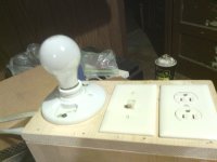
Start by building a light bulb current limiter, to stop blowing fuses and being able to measure *something*:
Light Bulb Limiter
Light Bulb Limiter
Plugging in a shorted cable in the Preamp in didn't produce anything I can report other than silence.BR.
I didn't say to short the preamp output. That could be really bad for the preamp. I said to plug the preamp output into the guitar input of your other amp, just be careful to keep the volumes reasonable. You should be able to play guitar thru that setup, just preamping twice in series. You should eventually hear the cracking noise from the other amp, because now the other amp is playting the 'noisy' preamp. When the noise moved with the preamp outout that proved the noise starts in the preamp.
As far as the power problem, that's a different subject, and needs some measurement.
I didn't say to short the preamp output. That could be really bad for the preamp.
EXTREMELY unlikely, and a quick glance at the circuit shows 100% definitely not - but even without the 1K resistor it would be unlikely to cause any damage anyway. The 1K would also prevent shorting the preamp out socket from helping at all.
However, I suggested sticking a plug in the PA IN socket, which makes a lot more sense as it disconnects the preamp from the power amp and isolates the problem.
The joints I thought I had shorted are a ground leg for one of the pots and the ground leg of the adjacent "More Drive" switch.
If there is something shorted from my endeavors I cannot locate it.
I got more 4 amp fuses and removed the PCB from the chassis and hit the on switch and it just hums and then pops the fuse after a few seconds. I'm pretty sure what's happening now is what was going to happen eventually anyway. It used to blink out and hum intermittently, now its doing it non-stop.
I would suggest almost certainly not - it's likely it's something you did, and have blown the power amp.
A DC coupled transistor amp is like a chain of dominoes, any slight short you caused makes them all fall down.
However, the described location probably shouldn't affect the power amp?.
Anyone have enough understanding of how to troubleshoot this? I have a Good quality DVOM.
For a start check to see if the output transistors read S/C or low resistance.
Reply to Nigel
Nigel
I don't think I did anything detrimental to my amp. Of course I could be wrong on that but I have been looking over everything that I touched and I haven't shorted anything that I can see. The joints that I reflowed are all in the area where the power supply connects. Everything in that area is spaced apart. Not is no chance anything in that area is shorted from what I did. Now there is the chance that I cause the existing/pending problem (intermittent loud hum associated with the amp "shorting out" and becoming non-operational) The only difference now is the non-operation and hum is constant and its blowing the fuse. At this point it doesn't really matter what caused it, I either figure out how to troubleshoot this or it becomes a parts donor. I have to figure something out because I can't afford to buy a new amp at the moment and the one I have left sounds like crap.
I am heading out to my shot to build the light tester thing mentioned yesterday. Hopefully that will allow the amp to stay on long enough to troubleshoot the issue.
BR
It wasn't blowing fuses before, and now it is. That is almost certainly due to something you did. It happens to us all. I*t would be a supreme coincidence if the amp randomly developed a new problem at the exact time you took it apart and put it back together.
COmmon problems would be something like the heat sink shorting out a power supply rail due to a torn/damaged/missing insulator under a power transistor. Also, push-on connectors from the mains wiring or transformer wiring on the wrong pegs. Loose hardware touching the underside of the board. Loose solder beads, etc.
COmmon problems would be something like the heat sink shorting out a power supply rail due to a torn/damaged/missing insulator under a power transistor. Also, push-on connectors from the mains wiring or transformer wiring on the wrong pegs. Loose hardware touching the underside of the board. Loose solder beads, etc.
FM212R
JMFahey I built the current limiter. Picture is attached.
I understand what's its supposed to do but I am not sure how to check the amp (if it will fire up without blowing the fuse)
Nigel I'm not sure what s/c stands for. Its probably obvious but I have a cold at the moment and my head is pretty cloudy.
Enzo I agree, its probably something that I caused. I said I didn't think it is because its doing what it would do every so often and of course now its blowing the fuse on top of that. My thinking is that I have disturbed it several times by taking it apart. I may well have just disturbed it enough to do what it was eventually going to do anyway. It has been getting gradually worse. It my have been right on the verge of blowing the fuse before I began messing with it. But in all fairness evidence suggests that I have done something and I'm just not recognizing it yet.
I remembered something today. 5 or so years ago when I first began having issues with this amp, the first issue it presented was when I was at church. I would play my Carvin through input 1 and my mic through input 2. I used the clean channel at church and every so often it would switch to overdrive for a moment and then switch back to clean. I never had the foot switch hooked up when that would happen. Fact is I rarely used the foot switch back then. I mainly used the clean channel and only used overdrive when I felt like making some noise and then I normally just used the button on the panel to switch it. Now I use some level of overdrive about 85 percent of the time. Everyone says its ok to have a high ohm load at the speakers than is factory set. But I have to take notice here that I have been running the speakers in series instead of parallel for the couple of days before this amp quit all together.
I am currently reading a book called How to hotrod your Fender Amp. It revolves around Tube amps but I read today that its bad to turn the amp on without the speakers attached. I did do that right after I reflowed some of the joints. It was only on for a few seconds but I did do it. Not sure if its bad to do that on a SS amp though.
I sure do hope we can figure this out. I know its just an SS amp and everyone talks bad about them but I gotta tell you, I have always loved this amp, It doesn't have as fat a sound as a tube but I can make some pretty kick *** tones with this one. But if it doesn't work out I guess it will be that much sooner before I get a Deluxe or Deville or Belair. .
Attachments
Nigel You said
For a start check to see if the output transistors read S/C or low resistance.
The power limiter works, I can turn the amp on and it doesn't blow the fuse.
So how do I check the output transistors?
Is there a possibility I damaged the diodes next to the power supply connections? D53.54.55.and 56 are all right next to the two large Capacitors next to the power supply connectors. I don't know how sensitive these items are. They are all beefy. I can't imagine them being damaged by simply reflowing the joints. I use a 30 watt pencil iron. It doesn't take but a second or so to flow the solder. I know things can be damaged with heat but I have been soldering much smaller items for several years and never burned anything up by over heating them with the iron. Of course these is always the first time... Just wondering.
So should I insert a plug into the preamp in or out and separate the pre and power and and see if it blows the fuse? Not sure where to go from here.
BR
Hey Badraven,
see your having a bit of a problem with your amp.
I fixed one with exactly the same problem. It's 4.45 here and I can't sleep. I'll have a look at my notes when I get to work in the morning.
As far as I remember, it is to do with something noisy on the power supply rail for the pre section, that is why you can hear it with a guitar plugged in the power amp, but at a much reduced volume- it is not interferring with the audio, but is modulating the power supply rail (I think the phase splitter has + and - 15 rail in common.
And whoever suggested plugging in to the power amp to isolate- bravo- that is exactly what I did to get to it.
And I've just remembered-I think it's the zener diodes d57/58 - cheap horrible way of regulationg power, and they get noisy. I replaced them with 78/7915- cheap voltage regulators.
So either one of those may have failed, and be taking out the fuse. Measure across them with your meter on ohms or diode test.
Also test the output devices (the larger 3 pin devices on the heat sink). Meter check of a transistor : Bipolar Junction Transistors
Google is great for finding out how to do stuff")
Check between pins 4, 8 and ground on your chips. Likelyhood is you have some solder bridging something, or a zener is dead. Running solid state amps not connected to speakers is fine- most nowadays will run into a dead short as they are protected against such.
But let's be on the safe side and not try eh?
So either one of those may have failed, and be taking out the fuse. Measure across them with your meter on ohms or diode test.
Also test the output devices (the larger 3 pin devices on the heat sink). Meter check of a transistor : Bipolar Junction Transistors
Google is great for finding out how to do stuff
Check between pins 4, 8 and ground on your chips. Likelyhood is you have some solder bridging something, or a zener is dead. Running solid state amps not connected to speakers is fine- most nowadays will run into a dead short as they are protected against such.
But let's be on the safe side and not try eh?
Nigel You said
For a start check to see if the output transistors read S/C or low resistance.
The power limiter works, I can turn the amp on and it doesn't blow the fuse.
So how do I check the output transistors?
You don't need a current limiter, you simply check them using the ohms range of your multimeter - with the power disconnected - otherwise you can't read resistance, and you would blow the meter as well.
S/C stands for 'short circuit' - basically zero ohms or near.
You should initially check between collector and emitter of the output transistors.
Dear badraven, let's not mix 2 different troubleshooting avenues, or it will become confusing.
1) without load (speaker) connected, turn the amp on plugged into the current limiter, whether it blinks or stays brightly lit already is an indication, and the do some *voltage* measurements.
The first 3 are voltage at the +V and -V rails (+42V , -42V) and the DC voltage at the speaker output one (P1 spkr wht).
Post your results.
2) now with amp off, even better unplugged, you will take some resistance readings.
To be more precise, we will use the "Diode test" setting, which applies a couple mA to the probes and shows the voltage reading between them.
We will measure the big suspects, the output and driver transistors.
We *expect* to find around 0.65V (650mV) across BE and BC junctions, one way; open or much higher (over 2V) the other way, and also open CE, both ways.
If any reading in a transistor is close to "0", it's an immediate suspect.
Carefully remove it and remeasure "outside".
You must measure: Q18/19/20/21 ; also check (in the regular 200 ohms scale) that R109/112 are not open.
Your multimeter will probably show a higher value, say 1/2 or 1 ohm, but that's fine, regular multimeters also add their own internal resistance (wiring/cpnnectors/switches/probes) which never is "0", what we don't expect there is "open" or a *large* value , sy 10 ohms or more.
Post results.
PS: just as an extra test, measure resistance to ground from Q20/21 collectors.
We don't want to find them shorted to ground.
Attachments
Transistor ohms Check
The 4 transistors on the heat sink are from left to right:
Pin convention all four: (L - R) A B C
Q20 (chip marking C3263) A - B = 28.5 ohms, B - C = 0, A - C = 28.3
Q18 (C3298) A - B = 4.46, B - C = 28.5, A - C = 4.49
Q19 (A1306A) A - B = 4.46, B - C = 0.1, A - C = 4.46
Q21 (A1294) A - B = 0.1, B - C = 0, A - C = bounces 0.1 - 0.2
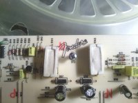
In the second pic there are two resistors R144 and R145
R145 has a deformation on top. It isn't burnt or discolored but it is deformed on top. It may be a casting flaw or something like that but I am bringing it to your attention just in case its something to worry about.
R145 = 328 ohms
R144 = 341 ohms
The 4 transistors on the heat sink are from left to right:
Pin convention all four: (L - R) A B C
Q20 (chip marking C3263) A - B = 28.5 ohms, B - C = 0, A - C = 28.3
Q18 (C3298) A - B = 4.46, B - C = 28.5, A - C = 4.49
Q19 (A1306A) A - B = 4.46, B - C = 0.1, A - C = 4.46
Q21 (A1294) A - B = 0.1, B - C = 0, A - C = bounces 0.1 - 0.2
In the second pic there are two resistors R144 and R145
R145 has a deformation on top. It isn't burnt or discolored but it is deformed on top. It may be a casting flaw or something like that but I am bringing it to your attention just in case its something to worry about.
R145 = 328 ohms
R144 = 341 ohms
Attachments
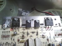
Well, Q20/21 are definitely shorted (it's what was expected anyway ), must be replaced.
Q19 is also shorted and Q18, although it might be alive, should be replaced anyway because it probably overheated anyway.
No problem but next time let's call transistor pins B-C-E (as shown, left to right) to avoid a possible extra source of confusion.
Please check R109/112 are not open.
R144/145 are not shown on the cropped schematic I posted, but I think they are the voltage droppers to get +/-15V rails .
The measured value is consistent with the ¿470 ohms? original value, so they look fine.
That small imperfection looks like a casting drop, nothing dangerous.
Ok, keep testing and order replacement transistors + micas/grease, whatever you need to mount the new ones.
The FM212 is a nice good sounding little amp, quite well made , typical Fender product, its only problem is that its production cost in a robot factory is so low, that Fender is not too keen on repairing it, after warranty time.
Delights of globalisation.
Good luck.
), must be replaced.Q19 is also shorted and Q18, although it might be alive, should be replaced anyway because it probably overheated anyway.
No problem but next time let's call transistor pins B-C-E (as shown, left to right) to avoid a possible extra source of confusion.
Please check R109/112 are not open.
R144/145 are not shown on the cropped schematic I posted, but I think they are the voltage droppers to get +/-15V rails .
The measured value is consistent with the ¿470 ohms? original value, so they look fine.
That small imperfection looks like a casting drop, nothing dangerous.
Ok, keep testing and order replacement transistors + micas/grease, whatever you need to mount the new ones.
The FM212 is a nice good sounding little amp, quite well made , typical Fender product, its only problem is that its production cost in a robot factory is so low, that Fender is not too keen on repairing it, after warranty time.
Delights of globalisation.
Good luck.
JMFahey Tests
I have a request for everyone. People keep using abbreviations and technical terms.
I understand we try to type as little and precise as possible but a lot of what you all are posting is "Greek" to me. I'm not stupid but I am playing catch up here. If you all could please be specific on what you want done. If you want me to take a voltage or resistance measurement please tell me the pin number(s) or the item designation as shown on the schematic. That way I know I am checking the correct item and am not wasting your time giving you wrong information. Thanks!.
When I run the amp through the limiter the fuse does not blow. The 75watt light comes on and it fairly bright. I don't think its as bright as normal but its not dim and it does not blink, its on steady.
Speaker output (speaker disconnected) reads .009 volts. (DC)
I am not sure which points you mean when you wrote "+V and -V rails" I think that means the power coming into the amp. On the schematic, power goes through the switch and then to P7 and P8
P7 = 114.5v
P8 = 120.4v
1) without load (speaker) connected, turn the amp on plugged into the current limiter, whether it blinks or stays brightly lit already is an indication, and the do some *voltage* measurements.
The first 3 are voltage at the +V and -V rails (+42V , -42V) and the DC voltage at the speaker output one (P1 spkr wht).
Post your results.
R109 = 0 ohms
R112 = .1 (20 scale)
The items listed below are my next tests.
I will order the resistors. Is there a recommended vendor or brand I should get?
Thanks!
BR
2) now with amp off, even better unplugged, you will take some resistance readings.
To be more precise, we will use the "Diode test" setting, which applies a couple mA to the probes and shows the voltage reading between them.
We will measure the big suspects, the output and driver transistors.
We *expect* to find around 0.65V (650mV) across BE and BC junctions, one way; open or much higher (over 2V) the other way, and also open CE, both ways.
If any reading in a transistor is close to "0", it's an immediate suspect.
Carefully remove it and remeasure "outside".
You must measure: Q18/19/20/21 ; also check (in the regular 200 ohms scale) that R109/112 are not open.
Your multimeter will probably show a higher value, say 1/2 or 1 ohm, but that's fine, regular multimeters also add their own internal resistance (wiring/cpnnectors/switches/probes) which never is "0", what we don't expect there is "open" or a *large* value , sy 10 ohms or more.
Post results.
PS: just as an extra test, measure resistance to ground from Q20/21 collectors.
We don't want to find them shorted to ground.[/QUOTE]
- Home
- Live Sound
- Instruments and Amps
- Fender FM212R Problems