Hello all!
I just built a 2-12 (2 x 8 ohm speakers) folded horn speaker cabinet and yes, its badass!
My question(s) revolve around wiring the amp/extension cabinet.
I have two guitar amps: Fender FM212R and Line6 SpiderJam. Fender = 4 ohms SpiderJam = 8 ohms. I wish to add a plugin on the back of each amp where I can plug in the speaker cable and disconnect the speaker(s) in the amp.
I purchased a Switchcraft 1/4" jack with what I think is referred to as a shunt. Its supposed to disconnect one circuit and redirect it when the cable is plugged in but I can not seem to get it to cancel the amp speaker when I plug in the cable.
Is there such thing as a switch I can wire into the circuit that will allow me to switch to different ohm loads? Or is there such thing as a jack plate that has several sockets with different ohm loads. I am trying to figure a way to make the extension box compatible with both amps and have the correct ohm load respectively..
I ended up wiring the box speakers in series which ended up being 12.6 ohms load.
- been learning that 8 ohm speakers rarely actually ohm out to 8 ohms.- Which accounts for the "strange" ohm load I have,
Wired in series works fine on both amps so far but I am concerned that having a 12 ohm load on the fender might be bad since it calls for 4 ohms from the factory.
Can I change the ohm load of a speaker by adding a resister to the circuit? For instance can I do something to a speaker externally to change it from an 8 ohm to a 16?
Why don't 8 ohm speaker actually ohm out to 8 ohms?
Is there someone here with knowledge on this subject or does someone here know where I can find the info I need to complete this project? Thank you in advance for your help!
badraven
An externally hosted image should be here but it was not working when we last tested it.
one of those should work, if i understood you correctly. or did you try that and it didn't work?
there are 4 pins
2 you connect from amp, these are raised up by jack. 2 you connect to internal speaker, these are on the nearside of pic. inserting jack disconnects internal speaker by raising the contacts up.
they cost pennies.
Thanks for the quick reply. Following is a link to the socket I used.
Mojo Jacks Switchcraft J12A 1/4'' Shorting Jack
I will try the one you suggest but I am not sure how I will mount something like that since its meant to mount on a circuit board.
Mojo Jacks Switchcraft J12A 1/4'' Shorting Jack
I will try the one you suggest but I am not sure how I will mount something like that since its meant to mount on a circuit board.
you can get them with solder tags too. the one you have looks like the same principle but only on the tip of the jack, which should work for what you want. Maybe you wired it up wrong.Thanks for the quick reply. Following is a link to the socket I used.
Mojo Jacks Switchcraft J12A 1/4'' Shorting Jack
I will try the one you suggest but I am not sure how I will mount something like that since its meant to mount on a circuit board.
How about this on the speaker end.......The impedence on any one driver is an ever-changing value...when one takes our trusty VOM we are measuring RE or a DC value. When the driver encounters an AC signal the impedences are all over the map...so to speak. When the AC signal at the bottom, say 40 Hz, rise to Thirty Ohms...or resonance, drop back down at say 300 Hz then rise again towards 3-10K.....the designation of "8 Ohms" is a rough average.
The 12 ohm load on the Fender is just wasting precious power.
I don't know the issue on the "speaker" jacks on the rear of the two amps....as set up by the factory they should cut out the "on-board" speakers because adding external speakers will increase the load seen by the amp....a no-no.
Try digging up a schematic of both amps, perhaps the two are set-up for external speakers( In parallel only)?????
(No I got that wrong, the jacks at the speaker end are just the plain types not switching)
___________________________________________________Rick.........
Attachments
Last edited:
Speaker Box
Richard
Thanks for the help. I don't understand the first part of what you wrote. But I am learning all this stuff so its just a matter of time.
The amps don't have external jacks, that is something I am adding by mounting a jack on the back of each and routing the speaker wire to the jack and then on to the speaker(s) respectively.
The issue with the external jack has been remedied, I found a very small spot of solder that had dripped down and shorted between two of the connecters. Not sure how I did that but I have corrected it and the internal speaker is canceled when I plug in the external speaker.
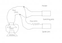
In the drawing you loaded it shows a 4 ohm resister on the SpiderJam, which I understand would bring the 4 ohm load of two parallel speakers up to 8 ohms. My question is: How do I determine the type of resister to use. I assume it needs to be 4 ohms but the resisters I normally see are 1/4 watt. Do I find 100 watt 4 ohm resisters? And where do I find something like that?
There is a small difference in the tone of the Fender going from a 4 ohm load to a 12.
I understand that the higher ohm load lowers the power output. The amp is actually rated at 90 watts at 4 ohms. So I think that makes the amp about 80 or so watts at 12 ohms, but I am not sure.
Richard
Thanks for the help. I don't understand the first part of what you wrote. But I am learning all this stuff so its just a matter of time.
The amps don't have external jacks, that is something I am adding by mounting a jack on the back of each and routing the speaker wire to the jack and then on to the speaker(s) respectively.
The issue with the external jack has been remedied, I found a very small spot of solder that had dripped down and shorted between two of the connecters. Not sure how I did that but I have corrected it and the internal speaker is canceled when I plug in the external speaker.
In the drawing you loaded it shows a 4 ohm resister on the SpiderJam, which I understand would bring the 4 ohm load of two parallel speakers up to 8 ohms. My question is: How do I determine the type of resister to use. I assume it needs to be 4 ohms but the resisters I normally see are 1/4 watt. Do I find 100 watt 4 ohm resisters? And where do I find something like that?
There is a small difference in the tone of the Fender going from a 4 ohm load to a 12.
I understand that the higher ohm load lowers the power output. The amp is actually rated at 90 watts at 4 ohms. So I think that makes the amp about 80 or so watts at 12 ohms, but I am not sure.
Attachments
Last edited:
you need to put a switch in the cab so it changes from series wired to parallel, which will give you a nominal impedance of 16 ohm (your 12.6) and 4ohms in parallel.
Adding a resistor just wastes power output so no better than 16 ohm all the time.
your 4 ohm amp will handle 16 ohms, just fine wont go as loud is all, but 4 ohms on the 8 ohm amp will overload it, may even let the smoke out.
Adding a resistor just wastes power output so no better than 16 ohm all the time.
your 4 ohm amp will handle 16 ohms, just fine wont go as loud is all, but 4 ohms on the 8 ohm amp will overload it, may even let the smoke out.
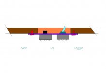
any double pole double throw switch will work. here's a diagram i nicked off of sum ones site . and ones of these should do the trick
Switch - Slide, DPDT, Replacement for Fender | Antique Electronic Supply LLC.
I'd prefer a rotary switch my self less likely to be knocked onto wrong setting. try your local electronics shop.
. and ones of these should do the trickSwitch - Slide, DPDT, Replacement for Fender | Antique Electronic Supply LLC.
I'd prefer a rotary switch my self less likely to be knocked onto wrong setting. try your local electronics shop.
Attachments
ArcticBreeze has the best & most practical approach here.....as one probably isn't concerned about absolute power output, an 8 Ohm output to a 16 Ohm load is "gentle" on an amplifier....this approach is the most logical.
On the illustrated wiring of the switch, ignore the "output jack" and the wiring part of it (Unless you want to add more drivers??). Like a big HF horn? (both set for 16 ohms...to get 8 Ohms)
Dual pole dual throw (DPDT) switches are everywhere...Radio Shack AKA ("rat Shack) They still have them!!...Individuals do recess mounting of switches often times...to prevent accidental activations.
____________________________________________________Rick.........
Attachments
Last edited:
- Status
- This old topic is closed. If you want to reopen this topic, contact a moderator using the "Report Post" button.
- Home
- Live Sound
- Instruments and Amps
- Speaker Box issues