Hi, I appreciate all of your information, however. I connected my Epiphone Valve special off the board exactly like you have for EL84's and 12AX7's and burned all of the 450 V caps on the board. Not sure what happened. I would like some advice perhaps on how to do it. The first place I saw said to connect only the 4 & 5's together on all. that didn't work just buzzing no sound. Then I tried your method after removing the jumpers that were on the board. And Smoked it.looking over photos of DIY projects on the net, and hearing the many stories about hum, makes me want to offer some observations that might help amateur builders.
Understanding the problem of tube heaters and hum is the first step toward ensuring your wiring job will be good enough to give happy results (no hum).
(1) The heater supply is usually A.C. (alternating current), a 50 or 60 cycle voltage taken from a winding off of the power-supply transformer. As such, it is usually more or less a sine-curve (but often with additional components, harmonics), but can actually appear as gross as a sawtooth depending upon the quality of your line voltage.
(2) For hi-fi and musical applications, the heater lines unfortunately provide a way in for noise from the mains (random hash, transients), and also radio frequency noise (RF), because the wires can also act as antennae, picking up noise from nearby motors and other equipment.
(3) So even if you don't convert your Alternating Current (A.C.) power to Direct Current (D.C.), you will still want to have some filtering and protection from line and radio noise.
(4) Also, if you don't convert to D.C., the 60 cycle A.C. hum will leak into other nearby circuits through the electromagnetic field coming off the heater wires, unless you take some precautions.
(5) As well, noise from other parts of the amp (the High Voltage HV supply, the screen supply and bias supplies) can also pick up and inject noise back into the heater lines.
(6) Many people don't bother to convert A.C. to D.C. for the heaters, and so other methods must be applied to minimize hum and noise. This is sometimes a cheaper solution.
In any case, hum and noise remains a problem with amplifier circuits, so basic strategies should be used.
Regardless of whether or not you convert A.C. to D.C. (removing most of the hum), the Mains coming into the amp should be filtered and/or isolated from line noise. This can be done with a basic capacitor network on the lines.
It can be built into the line plug:
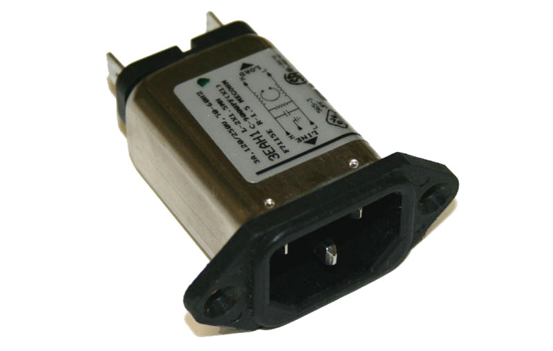
-----------------------------------------------------
Next, comes the layout of the heater wiring itself.
(1) The A.C. supply wires are twisted together, to collapse and minimize the field around each. At the same time as current flows in one direction on one line, it is returning in the opposite direction on the other line, and the two fields interact and cancel each other out.
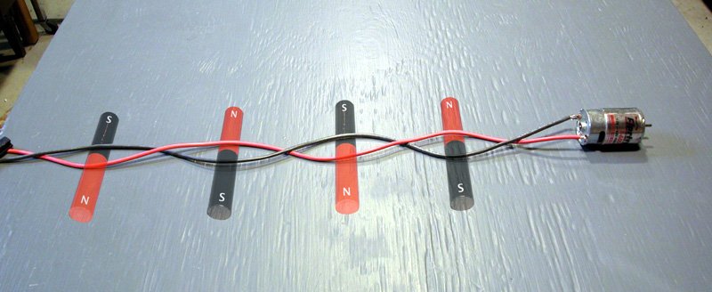
(2) But there is ANOTHER reason why the wires are twisted together, which is often forgotten or neglected: It also stiffens the delivery system and minimizes movement of the wires. What movement? Any motion in a wire carrying current, or in a magnetic field generates a signal, or creates a coupling field. The motion can be very small, almost invisible, as in a guitar or violin string. It will still be very significant here.

The practice of twisting wires is also done to greatly stiffen them, minimizing motion and coupling fields.
(3) This is also the reason why SOLID wire (such as 18 to 14 gauge) should be used for heater leads. In fact, any and all electrical activity has an impact on all metal in the area, and in case you haven't guessed it, will also cause physical forces of motion on the wires. Here we DON'T want flexibility, but rather stiffness.
If you doubt this, or think it is insignificant,
try loosening the bracing bolts on your power transformer,
and listening to the horrible vibrating rattles as the E-I sections bounce around.
(4) Getting back to the theory behind twisting the wires, We want to recognise also that the number of twists is also strongly related to the DISTANCE to the next object that might pick up the signal, by the Inverse Square Law:
Quote:
"The circuit is essentially a coreless electromagnet with only a single turn of wire. By twisting the wires, we produce many small electromagnets, instead of one large one. Furthermore, these many small magnets are pointing in alternating directions. If we were very close to one of these magnets, we could still detect it, but once we are a small distance away, the adjacent opposing magnets will cancel it out (figure 3)."
Thus we want as many twists as possible (per inch), to minimize the proximity effect to other nearby objects.
On the other hand, if you twist the wires too tight, you can also short them or break them or weaken them to the point where they generate resistance and heat unevenly, so there is a limit to how much you can coil / twist the wires before you risk damaging them.
Now we are ready to understand why many seemingly good efforts at heater-wire dressing fail.
The hum is directly related to distance:
(1) The most sensitive components are the ones closest to the heater wire. That would be the area right around the socket! This is typically where the twisting-dressing technique is done the most poorly and sloppily!
(2) Wires at a right-angle to the heater-wire are the least sensitive to hum. Often wires and components are laid out badly in regard to this obvious issue: orientation.
(3) Other components may or may not be more or less sensitive to heater hum depending on orientation. THERE ARE NO general rules for this. For instance, its a bit tricky to orient a coil (or a cap!) for minimum hum, because it has a 3-dimensional field! Some components will be sensitive in ANY orientation, and must be shielded.


I will look at possibly using any other part of the remaining wires coming out of the transformer that might be used or the method of changing AC to DC for heater wiring, I would basically just like to get it running again at this point. Could anyone tell if when I checked the two Orange wires that are supplying 6.3V to the board, by checking continuity and it shows an open circuit does that mean absolutely that something is damaged in the Transformer, or am I missing something. Oh, the initial method I used for connecting the heater wires came from the forum, titled heater wiring good bad and ugly, the poster had all really good pictures and everything, and the same board as mine, connecting pins 4 & 5 of the EL84 to pins 4 & 5 of the 12AX7s, and pre-amp tubes 4 & 5 are linked together. ???? Why didn't that work???
increasing gain on Epiphone Valve
So, I had a week and a half of reading and finally got my what I thought was ruined Valve Special working again, I just hooked the heater wires from EL84 connections, 4 to 12AX7 #4, #5 of the first Pre-amp tube to #4 of second one. Then#5 EL84 to both #9's of the Pre-amp tubes, and voila, it seemed to take a really long time to heat up the first time then they came back to life. I still have about to same amount of hum as before, probably due to the routing, but it's not any worst. I have the DSP board taken completely off, it doesn't work anymore. Now, what I would like to know is how can I do some simple adjustments to open the amp up a little, a little more volume/gain if possible. Anyone ideas would be so helpful. I want to thank all of you who didn't not give me the whole answer but allowed me to find my own way. Slowly but surely. Thanks again.
So, I had a week and a half of reading and finally got my what I thought was ruined Valve Special working again, I just hooked the heater wires from EL84 connections, 4 to 12AX7 #4, #5 of the first Pre-amp tube to #4 of second one. Then#5 EL84 to both #9's of the Pre-amp tubes, and voila, it seemed to take a really long time to heat up the first time then they came back to life. I still have about to same amount of hum as before, probably due to the routing, but it's not any worst. I have the DSP board taken completely off, it doesn't work anymore. Now, what I would like to know is how can I do some simple adjustments to open the amp up a little, a little more volume/gain if possible. Anyone ideas would be so helpful. I want to thank all of you who didn't not give me the whole answer but allowed me to find my own way. Slowly but surely. Thanks again.
 Please post guitar amplifier threads to the Instruments & Amplifier thread rather than Valves / Tubes. The explanation for why is in the sub header at the top of each forum. Please read forum rules.. Also please don't post things that appear to be spam. (Your last post which was deleted)
 Please do not start any more threads about this issue, please post all further material related to this subject in this thread.
I've merged your prior posts about this amplifier into this thread to give it context. Thread retitled.
1: Start with a better (bigger speaker) for volume and more open sound....a little more volume/gain...
2: Play with the bias (cathode resistor) on the 2nd ax7 triode to look for the sound you want.
3: Go stupid like I did and put in an additional pentode (eg 6AK5) as a first stage in front of the AX7 for insane amounts of distortion.
4: Have fun
Cheers
JimG
- Status
- This old topic is closed. If you want to reopen this topic, contact a moderator using the "Report Post" button.