Hi!
I've had this idea for some time now, basically I want to satisfy the following needs in one box with relatively few components:
- Hearing myself (my bass) on stage with In-Ear monitors
- Being able to plug in a second monitor signal
- Silent practice at home to music from my computer (think vox amplug)
- Powered by usb/battery/DC-adaptor
- Low parts count, small box
- Stereo output
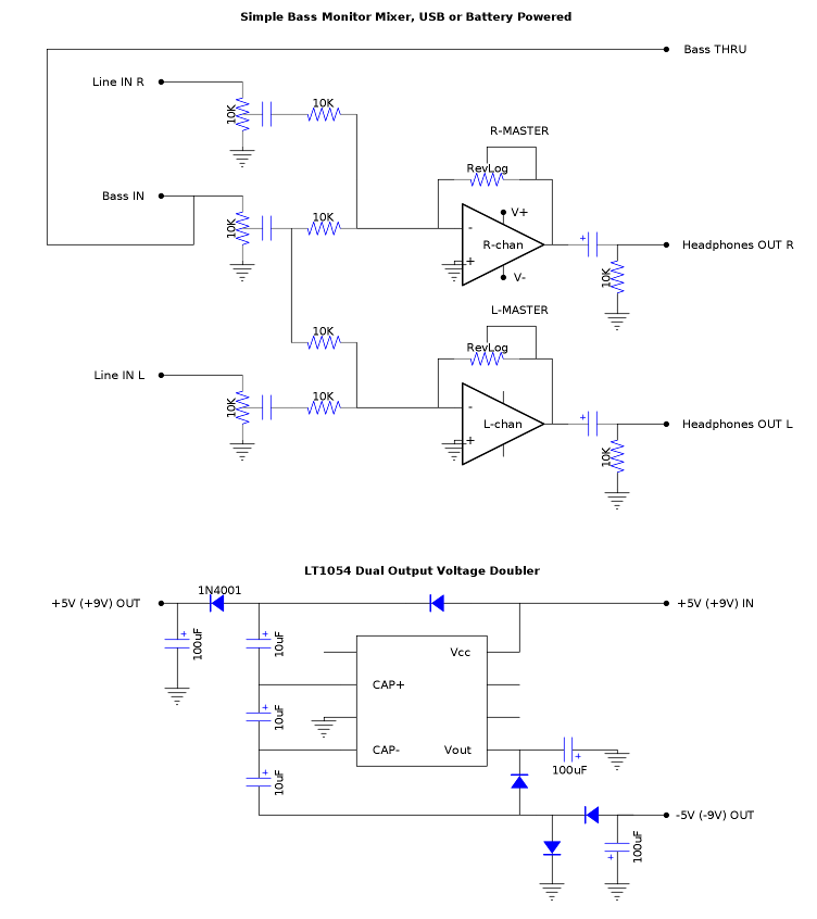
Since I want to be able to use different power sources, I thought to use a Voltage Doubler chip. This would give sufficient overhead when using USB as power source. (The reason I like to have USB-power is that I spend a lot of time using an amplug by the computer, and I'm getting tired of buying AAA-batteries.)
This would of course work with guitar as well, but a totally clean signal sounds a bit dull with guitar, so some tone shaping circuitry might be needed in that case.
I still haven't breadborded this design so I don't know for sure if it's going to work like this. Will I, for example, need a buffer for the Lo-Z bass signal? I also haven't used the LT1054 before so we'll see how it turns out. Opamp will probably be OPA2134, I'll use dual pots for line-in and master and a single for bass, so there would be three knobs.
Feel free to comment!
/Fredde
I've had this idea for some time now, basically I want to satisfy the following needs in one box with relatively few components:
- Hearing myself (my bass) on stage with In-Ear monitors
- Being able to plug in a second monitor signal
- Silent practice at home to music from my computer (think vox amplug)
- Powered by usb/battery/DC-adaptor
- Low parts count, small box
- Stereo output
Since I want to be able to use different power sources, I thought to use a Voltage Doubler chip. This would give sufficient overhead when using USB as power source. (The reason I like to have USB-power is that I spend a lot of time using an amplug by the computer, and I'm getting tired of buying AAA-batteries.)
This would of course work with guitar as well, but a totally clean signal sounds a bit dull with guitar, so some tone shaping circuitry might be needed in that case.
I still haven't breadborded this design so I don't know for sure if it's going to work like this. Will I, for example, need a buffer for the Lo-Z bass signal? I also haven't used the LT1054 before so we'll see how it turns out. Opamp will probably be OPA2134, I'll use dual pots for line-in and master and a single for bass, so there would be three knobs.
Feel free to comment!
/Fredde
LM386 works fine from 5 to 9V if all you have to drive is 32 ohm headphones, no need to raise supply nor make split rails.
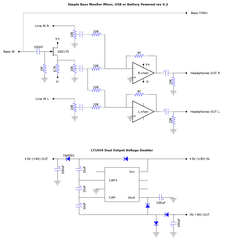
You should add an input buffer for the Bass signal, so you can also plug passives there.
A simple source follower FET will do.
Select it for Vp between 2 and 3 V so basically it self biases there with a 4K7 to 10K source resistor.
And your master volume should be a classic passive one at the input of the chip, not an active feedback one.
Thanks, yes I have some LM386's handy, it would indeed be simpler. But there goes my excuse to try out the LT1054LM386 works fine from 5 to 9V if all you have to drive is 32 ohm headphones, no need to raise supply nor make split rails.
You should add an input buffer for the Bass signal, so you can also plug passives there.
A simple source follower FET will do.
Select it for Vp between 2 and 3 V so basically it self biases there with a 4K7 to 10K source resistor.
And your master volume should be a classic passive one at the input of the chip, not an active feedback one.
")
But I'll definitely add a FET-buffer. And I've been thinking the master vol is pretty much redundant with only two channels. Might just settle on a suitable gain and use the input levels only.
I'm having some second thoughts about the LM386. Can it be used as a summing amplifier by itself or would it require an inverting stage first? Also, even if it does work by itself, it's still a single amp chip so it would require two of them which is as much space as a dual opamp plus voltage converter.
I'm having some second thoughts about the LM386. Can it be used as a summing amplifier by itself or would it require an inverting stage first? Also, even if it does work by itself, it's still a single amp chip so it would require two of them which is as much space as a dual opamp plus voltage converter.
An LM386 is a small power amplifier, not advisable to use it as a preamp anyway - it's NOT an opamp.
Exactly. So it would require a preamp, and the parts count would begin to get out of control...An LM386 is a small power amplifier, not advisable to use it as a preamp anyway - it's NOT an opamp.
For now, I think I'll stick to my original plan. Added the input buffer (2SK170 is what I have in my drawer) and removed the master vol completely:
Just built the LT1054 voltage doubler on breadboard (exactly as this schematic, which is straight from the datasheet), and it works. I had misunderstood it's functionality slightly, it doesn't double as in +5V to ±5V, it doubles +5V into ±10V (or roughly ±9V as there is a slight voltage loss that increases with load). With a (half depleted) 9V battey it measured about ±16V.
I got a higher reading on the positive rail (almost 1 volt more than on the negative). I don't know why this is happening, but It's nothing I will lose sleep over. One could regulate but I'd call that overkill in this case.
I also tested it "for real" to power one of my DIY preamps (a JFET build), and it worked perfectly without the slightest hiss or hum. (This preamp has an opamp output buffer, though, so it's not very noise sensitive.)
I didn't say you use it as an Op Amp but as a headphone driver
And you need no active mixer, *at all*.
Simply 2 mixing resistors to the LM386 .
It has lots of available gain anyway.
For 1V RMS at the headphones (realistic given the 5V supply), 20X gain means you need 50mV at the input, or 100mV at the left end of each 10K mixing resistor.
And you still have 20X dB *extra* gain available at the LM386, although you don't need them at all.
And yes, you will need two LM386 ... but nothing else.
Your 2SK170 stage will work happily from 5V to ground.
But of course, if you want to play with LT1054 , go ahead and do it, probably I'd also do the same.
It's just that I'm such a minimalist
Oooops !!! Simulposting
And you need no active mixer, *at all*.
Simply 2 mixing resistors to the LM386 .
It has lots of available gain anyway.
For 1V RMS at the headphones (realistic given the 5V supply), 20X gain means you need 50mV at the input, or 100mV at the left end of each 10K mixing resistor.
And you still have 20X dB *extra* gain available at the LM386, although you don't need them at all.
And yes, you will need two LM386
... but nothing else. Your 2SK170 stage will work happily from 5V to ground.
But of course, if you want to play with LT1054 , go ahead and do it, probably I'd also do the same.
It's just that I'm such a minimalist
Oooops !!! Simulposting
Last edited:
Well I have to, I already bought two of them and they are expensiveBut of course, if you want to play with LT1054 , go ahead and do it, probably I'd also do the same.
It's just that I'm such a minimalist
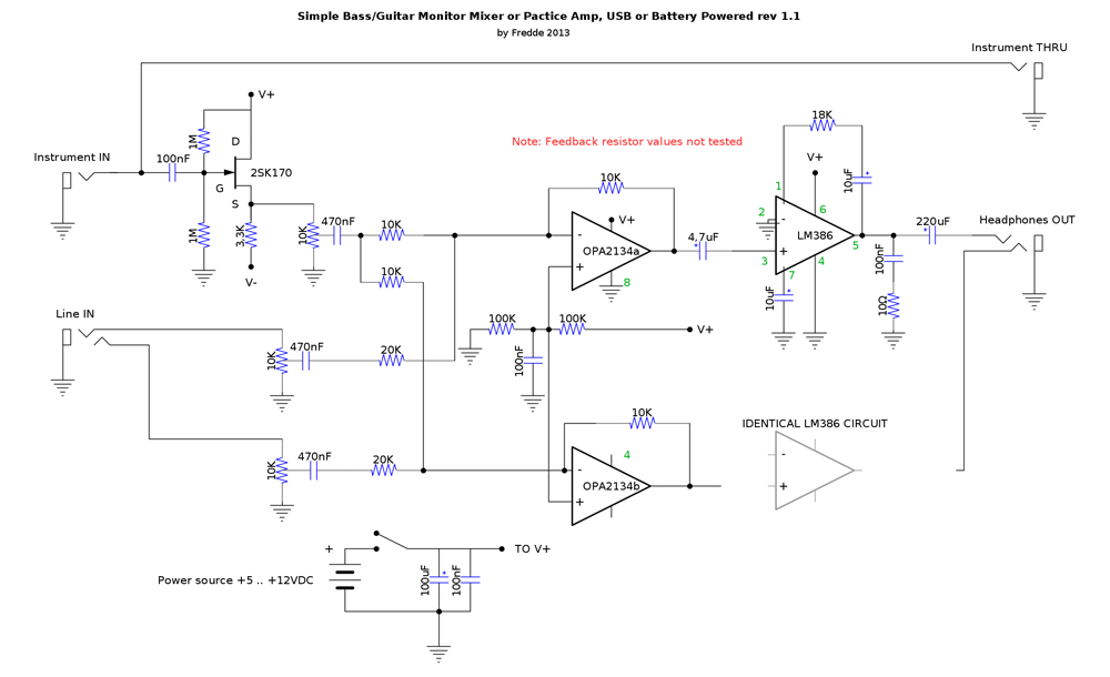
But mostly because I don't find the LM386 that exciting. I use it pretty regularly, but usually just as a quick tool to get some output when testing something on a breadboard (with arduino for example).I've decided to bite the bullet and make a separate output stage with an LM386. This way there shouldn't be any need for the voltage doubler since the OP2134 should work with +/-2.5V and there isn't need for much headroom when the opamp stage is low gain.
The rather uncommon way of using the LM386 (with a resistor between pins 1 and 5) is to make the gain less than the factory set 20. I got the idea from here: HeadBanger Headphone Amp Construction Kit, but I've seen it elsewhere too.
So this is what it looks like, note that I haven't tested this version on breadboard yet so it's likely there will be some changes:
In this case (split supply) it's not needed.
Its function is to raise the Source voltage (by raising the gate voltage) in single supply circuits, to raise the input signal handling.
Bootstrapping?
Maybe, if you want to raise input impedance.
Not really needed here, because 1M from Gate to ground is fine.
Its function is to raise the Source voltage (by raising the gate voltage) in single supply circuits, to raise the input signal handling.
Bootstrapping?
Maybe, if you want to raise input impedance.
Not really needed here, because 1M from Gate to ground is fine.
some suggest to bootstrap the jfet buffer ?
(don't know if it makes sense)
No it doesn't, pretty pointless with an FET.
can I ask...what is the 1M from drain(power) to base(input) doing ?
I know other curcuits use it, but is it needed with these jfets ?
Again, seems pretty pointless, just the single resistor to ground is all that's required - and it could be increased to increase input impedance, meaning there's no need for bootstrapping (which is what you'd do with a bipolar input in order to give a higher input impedance).
I don't know about bootstrapping, but the two 1M resistors between ground and V+ create a reference voltage. The V+ to base resistor wouldn't be needed in a dual supply configuration (I could also skip it and connect the base to ground resistor to the opamp's voltage divider).some suggest to bootstrap the jfet buffer ?
(don't know if it makes sense)
can I ask...what is the 1M from drain(power) to base(input) doing ?
I know other curcuits use it, but is it needed with these jfets ?
Good info about fet-buffers: Basic Buffers
Again, seems pretty pointless, just the single resistor to ground is all that's required - and it could be increased to increase input impedance, meaning there's no need for bootstrapping (which is what you'd do with a bipolar input in order to give a higher input impedance).
Isn't a vref bias better than ground? It might be pointless in this case, but that's beyond my knowledge. I've made buffers like this before and they've worked fine, so I didn't see any point in modifying the circuit.
That buffer is actually the thing I'm the least unsure of about this design.
EDIT: Just noticed a typo in the schematic, the 3k3 source resistor should of course go to ground, there's no negative supply in the design anymore (but the 1M resistors still stand).
Last edited:
Isn't a vref bias better than ground? It might be pointless in this case, but that's beyond my knowledge. I've made buffers like this before and they've worked fine, so I didn't see any point in modifying the circuit.
It just seems a waste of a resistor?, you're wanting a negative bias on the gate - achieved by the voltage drop across the source resistor - biasing the gate positive doesn't seem a very good idea?.
It's not something you normally see used commercially.
That buffer is actually the thing I'm the least unsure of about this design.
EDIT: Just noticed a typo in the schematic, the 3k3 source resistor should of course go to ground, there's no negative supply in the design anymore (but the 1M resistors still stand).
Try taking the top resistor out, and see if you can tell any difference
According to the webpage you linked it's supposed to improve large signal handling, but it could just as well make it worse
Either way shouldn't make a great deal of difference.
Sorry but it's very much used commercially.It just seems a waste of a resistor?, you're wanting a negative bias on the gate - achieved by the voltage drop across the source resistor - biasing the gate positive doesn't seem a very good idea?.
It's not something you normally see used commercially.
And the point is, as I said before, to improve input signal handling.
Another important point is to make biasing and signal symmetry more predictable, without time wasting individual tweaking or obsessive Fet matching.
DIYers, of course, add a so called "biasing" preset to every Fet stage
The impact of the existance or removal of this resistor goes a bit beyond my scope, but I have another question:
Since this amp is going to be used live on stage, it would be very nice to have some kind of limiter so that I don't become deaf when the singer drops his microphone, or when the sound guy accidentally bumps the monitor feed.
One way to achieve this seems to be using a diode clipper. (A collection of circuits here: Designing A Limiter For Headphone Amplifiers | HeadWize)
Is this a good idea? One obvious problem is the difference in efficiency amonst headphones, it would clip too early on some and too late on others if the clipper is placed at the output, right?. If it's placed at the input, it would work only relative to the input signal, not in absolute terms.
I'm open for suggestions here, but the design cannot be anything too fancy, because I need the design to fit in a small enclosure.
- Status
- This old topic is closed. If you want to reopen this topic, contact a moderator using the "Report Post" button.
- Home
- Live Sound
- Instruments and Amps
- Project: Simple bass guitar headphone monitor mixer