Is AC "mains" polarity affecting amp to amp hum?
So, I harvest IEC sockets from old computer power supplies and use them to upgrade old amps from 2 to 3 prong. I know that I should run the switch and fuse both on the "hot" side of the AC, but are there any other considerations once the AC gets to the transformer?
I'm asking because I noticed last night that when I turned on my bass amp, my guitar amp started to hum louder. It had a small amount of hum already, but it seemed to double when the bass amp was powered up.
The bass amp is factory made, Ampeg SVT. The guitar amp is my own DIY conversion
There's so much confusion and misinformation on this subject I dread getting involved....
But, to get off to a proper start, are you absolutely positive that the two sockets you're plugging in to are properly wired? (Yes, this means examining the outlets' wiring and checking the fuse box if there's any chance they're not on the same circuit.)
But, to get off to a proper start, are you absolutely positive that the two sockets you're plugging in to are properly wired? (Yes, this means examining the outlets' wiring and checking the fuse box if there's any chance they're not on the same circuit.)
no connection between the two amps
i'll check the outlets with ye olde outlet tester.
beyond putting the fuse and switch on the "hot" lead of the mains wiring, are there any other considerations? i'm really just concerned to "get it right" in regards to wiring my own designs, or putting IEC plugs on previously 2-prong equipment.
i'll check the outlets with ye olde outlet tester.
beyond putting the fuse and switch on the "hot" lead of the mains wiring, are there any other considerations? i'm really just concerned to "get it right" in regards to wiring my own designs, or putting IEC plugs on previously 2-prong equipment.
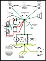
As far as putting IEC plugs on old equipment, I take a dim view of the practice as it engenders a false sense of security. There's no point to the third wire unless you have a conductive case that's separate from the chassis (that's also part of the IEC standard). Note the diagram tauro0221 posted, the circuit between the case and ground, and the admonition that inputs not be connected to the chassis. I've never seen a guitar amp that meets these conditions. By adding an IEC cord to an old amp you're just running a second ground wire between the same two points. Redundancy can be good, but in this case I think it's silly.i'm really just concerned to "get it right" in regards to wiring my own designs, or putting IEC plugs on previously 2-prong equipment.
Some people seem to think there's magic in that third hole in the outlet, but unless you live in new construction in one of the few states that supports the latest standard, you'll find that extra wire goes to the same buss in your fusebox the normal ground does.
As to your new builds, by all means follow the IEC specs. The amps will be safer and should hum less.
Tauro - I essentially follow the same star ground concept you posted. I do connect the speaker grounds to the star ground point. all jacks, input and output, are isolated from the chassis. i don't use pot-backs for ground. i bolt the green earth wire with a locking washer to the chassis with one of the IEC screws. I don't have any wire connecting the Earth to the Audio signal ground nor the star ground "bus" point indicated in the illustration. I also don't have all the items shown on the Earth "bus" - the .01 cap, 10 ohm resistor, diodes. I got my star grounding information primarily from Aiken Amplification and from Valve Wizard, with some other reading here and there.
What i'm getting is a lot of concern for my grounding scheme, but what I'm asking about is specific handling of the "hot" line of the AC. I'm deducing that running it through the fuse, then the switch, then to the power transformer - that's about it as far as concern for "phase" relations between other equipment. That is, operating under the assumption that my house wiring is correct with no inverted/reversed outlets. I do need to check my house wiring and correct any found issues.
The amps that I've put IEC plugs on previously had socket/cord connections that were two-prong, without the "polarized" larger prong. The old cords were cracking and overly rubbery and felt cheap. However, thanks Keriwena for the information on the "magical" third prong. I'd just recently read that same info, which is in part what got me concerned about AC polarity.
Thanks for your input and time!
It is difficult to buy new PVC two prong AC cords in the US. One source was apexelectronic.com at one time. When one adds a 3rd pin cord to a Hammond organ, one is supposed to check leakage current between the chassis and safety ground. > 40 microamps, bad. The cotton insulated mains transformer before 195? was prone to rotting in wet environments and causing much leakage. The leaky transformers were a danger to the organ player if they also used a microphone connected to a grounded system, but adding the third wire made the leakage constant in the transformer and tended to make them break down and blow the breaker (house breaker, no internal fuse). How old is your instrument amp? My 1961 dynakit equipment has cotton insulated transformers, but has never been wet.
Some old music equipment has competent signal grounds, some cheap old guitar amps run a lot of things helter skelter to the chassis without much thought about the star configuration. I helped a kid in Saskatchewan, lots of lovely pictures of the badly designed old amp he was recapping. He was successful, however, one more year.
The 3rd wire of the outlet going to the same place in the AC breaker box is not a problem in the US. The round pin and green wire are not suppose to carry current. The white wire and big blade are at the same potential roughtly but are supposed to carry current. If current is detected in the green wire, fault, time for analysis and repair. Many home repair people, however, install 3 pin sockets (because that is all that is available) on 2 wire Romex in the wall. Bad practice.
Last edited:
thanks for the info Jo!
I'm not sure on the insulation of the transformer. It appears as solid as any modern transformer I've seen, though it is from the 50's or early 60's. How could I tell if it had paper insulation?
The amp is out of an old Bell & Howell 202 projector, and they hung the transformer in the top of the projector case above the projector and run the wiring through an 11-pin connection.
who here uses the ground breaker in Tauro's post? any luck with it?
The best way to detect deteriorated insulation, cotton or whatever, is to isolate the frame from the neutral and put about a 10 k resistor between them. Measure AC voltage across it- that is the leakage current. V/R=I the current. Hammond liked about 40 microamps or less. Ground fault outlets trip at about 140 microamp wikipedia says.
You can see the actual cotton insulation coming out of the transformer on the leads. It has a weave to it. PVC insulation that replaced it is smooth.
You can see the actual cotton insulation coming out of the transformer on the leads. It has a weave to it. PVC insulation that replaced it is smooth.
- Status
- This old topic is closed. If you want to reopen this topic, contact a moderator using the "Report Post" button.
- Home
- Live Sound
- Instruments and Amps
- AC polarity