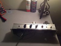
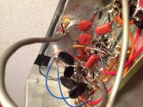
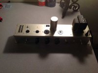
I know this already has a couple threads, but I can't get my answers from them. Here is a Silvertone Organ Amp Model 4721. I'm converting it over to a guitar amp. I have already changed over the pots and added a 1/4 input jack. Changed the on/off switch to an actual switch and going to add a standby as well. I removed the master volume and am going to add a tone knob to the middle pot. I changed all the electrolytic caps and I also changed out the paper caps. I left the ceramic caps as they all tested fine.
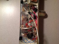
My problem is I can't get the tremolo to work. This layout is very strange to me. Any advice would be appreciated. Here are the pics. (The tube layout is: 12dw7, 12ax7, 6v6, 5y3)
Let me know if you need better pics. Thanks for any help!
-Steven
My problem is I can't get the tremolo to work. This layout is very strange to me. Any advice would be appreciated. Here are the pics. (The tube layout is: 12dw7, 12ax7, 6v6, 5y3)
Let me know if you need better pics. Thanks for any help!
-Steven
Attachments
 Hi Steven, Nice pix but I had to resize them, they were really big.
Please see here:
http://www.diyaudio.com/forums/everything-else/183084-pictures-why-not-attach-them.html
Cheers!
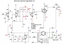
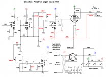
Yeah, that's why I'm trying to learn. I've just been looking at layouts which I know only shows where to connect things, not why. Here's a schematic I found a while ago, but it looks partially done. But I'll attach it anyways.
I think I going to just start by replacing the ceramic caps in that section to see if that helps.
I think I going to just start by replacing the ceramic caps in that section to see if that helps.
Attachments
That double .01 uf cap arrangement with a .022 uf cap going back from the plate of the V2 to feed the pi network looks just like a phase shift oscillator from the GE transistor manual seventh edition that I have been unable to make work. It is a cheap design oscillator that works sometimes, but not in any of the 7 versions I have tried. Do you have about 300V at the plate of V2? Is the 3mohm resistor very clean? Dust on a 3mohm can make a large difference in the value seen by higher voltage signals. (Your DVM measures at about 2V, usually). Same problem with the 10 mohm resistor coupling the oscillator output into the grid of the second half ot V2.
Having fooled with the phase shift one active element oscillator for months without success, I would make a better design 2 transistor oscillator to replace that one gain stage tube phase shift oscillator. You're not getting the classis "tube sound" out of an audio frequency oscillator, anyway. You can drop down 10 ma from the b+ to drive it with a resistor ladder, or rectify the filament 12 VAC to make a low voltage supply. Transistors are good for some things, just not as good at final stage amplification of guitar signals.
Having fooled with the phase shift one active element oscillator for months without success, I would make a better design 2 transistor oscillator to replace that one gain stage tube phase shift oscillator. You're not getting the classis "tube sound" out of an audio frequency oscillator, anyway. You can drop down 10 ma from the b+ to drive it with a resistor ladder, or rectify the filament 12 VAC to make a low voltage supply. Transistors are good for some things, just not as good at final stage amplification of guitar signals.
To add to indianajo's comments, and to firstly focus on the phase-shift low frequency oscillator - it would be good to check the following.
What is supply voltage at 'B'.
8K4 resistor is wrong - it should be something like an 820k.
The 270k//270k looks wrong - perhaps they are in series? - there would normally be something like 470k to 1Meg at that point.
Check the vibrato pot is 1 Meg (otherwise it will load the LFO too much).
Do you have a high-impedance probe to measure AC voltage to check if the LFO is oscillating (eg. by connecting to the vibrato pot wiper output) - eg. an oscilloscope probe with 1Meg input, or an AC meter with similar input impedance and measuring down to 100mV at 10Hz.
Some early LFO's appear to be marginal due to the 3M3 grid leak - increasing that value may help - or alternatively adding a cathode bias (eg. 2k2//25uF, or a red LED with on voltage about 1.5V to 2V).
Check the circuit around the cathode of the 12AX7 before the Volume pot - it's missing a cathode bias.
What are 'L?' ? (Are they the brown tube parts with yellow dot marking?)
Ciao, Tim
P.S. check the Magnatone Estey T-32 schematic - especially the vibrato modulator section with the varistors - see if that is similar to your circuit ?
Last edited:
I hate to disagree, but those single triode phase shift LFOs have been running fine for decades. A zillion Fenders use it, to mention just one.
I agree there ought to be some cathode bias resistor, and that odd connection for the cathode of the other half of the tube sure looks wrong.
Are those feedback caps among the ones you did not change? How did you test the ones you left? A hand meter will tell you the value, but not the ESR nor more importantly the leakage. Your meter runs on a volt or so, and a cap that checks fine at a volt could leak like a sieve at say 40 volts, and thus not work here.
This oscillator is a basic circuit and should work as built if it has good parts. And get the schematic right. When I encounter a dead trem oscillator, I verify the tube is conducting, and if it looks like the tube is working, I just wholesale replace that whole string of caps. Once I get the oscillator swinging, I can worry if the interface part works.
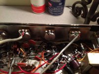
I think you switched the center taps on the power transformer. Connecting the4 HV center tap to the power tube cathode would be hard to defend. All the ripple current through the B+ would be added to the power tube. That should run straight to ground. ON the other hand, connecting the cente tap of the heaters to that cathode makes a lot of sense. It elevates the heaters to some DC voltage positive to ground, thus reducing potential for hum in the preamp stages.
Also, on the output transformer, that green tap with the couple resistors is hard to explain. You sure that connects to the primary?
I agree there ought to be some cathode bias resistor, and that odd connection for the cathode of the other half of the tube sure looks wrong.
Are those feedback caps among the ones you did not change? How did you test the ones you left? A hand meter will tell you the value, but not the ESR nor more importantly the leakage. Your meter runs on a volt or so, and a cap that checks fine at a volt could leak like a sieve at say 40 volts, and thus not work here.
This oscillator is a basic circuit and should work as built if it has good parts. And get the schematic right. When I encounter a dead trem oscillator, I verify the tube is conducting, and if it looks like the tube is working, I just wholesale replace that whole string of caps. Once I get the oscillator swinging, I can worry if the interface part works.
I think you switched the center taps on the power transformer. Connecting the4 HV center tap to the power tube cathode would be hard to defend. All the ripple current through the B+ would be added to the power tube. That should run straight to ground. ON the other hand, connecting the cente tap of the heaters to that cathode makes a lot of sense. It elevates the heaters to some DC voltage positive to ground, thus reducing potential for hum in the preamp stages.
Also, on the output transformer, that green tap with the couple resistors is hard to explain. You sure that connects to the primary?
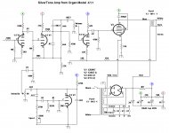
Ok, I printed out the schematic and followed it to the circuit of my amp and there are some differences. I don't know why I didn't do this to start with. I'm attaching the updated schematic to see if this looks any better. The things that differ from the one I posted earlier are in RED. Thanks for your help! I'm going to go ahead and change out all the ceramic caps though.
-Steven
-Steven
Attachments
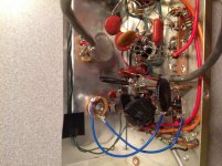
I took the other side of the panel off and could see a mistake I made in the new schematic. On the output transformer, there is blue, red, green, white, and a bare wire. They all come out the same side, but I think the Blue is to plate, Red is B+, green is to resistors then ground, white is secondary +, and bare is secondary -.
Does the green go into the screen? Like the pic I attached?
Does the green go into the screen? Like the pic I attached?
Attachments

I believed the schematic you drew with the screen going to B+(A) in post #13.
The fact the wires all come out of the transformer on the same side of it physically says nothing about how they are wired internally. In the post #14 above you show the green wire as a center tap of the primary./ That means it will have continuity with the red and blue wires. (Standard American color code for output transformers has primary wires red to B+ and blue to tube plate for single ended transformers like this) But in the post before that you have it as part of the secondary. You must determine with an ohm meter which winding - primary or secondary - this wire and resistors is part of. It can't be both.
And having those two resistors in series is weird. Any chance something was connected to the point between the two resistors where they join? I am imagining something like using them as a voltage divider to sample the signal off the speaker winding for use as a output for a slave amp. A sort of poor man's line out.
Ok, I got the vibrato working. When I took the voltage readings on the pins, obviously the problem was the plate at pin 6 on V2. I went back from there and found that the 270K resistor had opened. I replaced it and viola...vibrato. I'm going to add a speed pot so it can be controlled. Are there any suggestions to make it sound any better for those of you who know more about schematics than me?
I know I've been having a conversation with myself the last few posts here. Haha, oh well, here is the schematic as it is right now. Sounds really cool and everything works! Still wondering if there are some things I should do to make it more guitar friendly. Vibrato pitch shift is pretty cool and the speed pot help a lot. I've seen a 25/50V cap on the cathode of the 6V6. What purpose would that serve?
-Steven
-Steven
Attachments
None of your cathodes are bypassed, but any of them could be. It tends to raise the gain some and add to the bottom end response.
But really, if you wonder what a 25uf (or 22uf as a more common value) cap on the cathode of the power tube will do, tack one on there and find out.
Try adding one across the 3k9 cathode resistor of the first stage for a gain boost. You may like it or it may be going in a direction you don't like, but it is simple to try it and it isn't like it would be permanent if you hate it. I don't think that 220k is necessary at the input, I;d be happier with maybe 22k instead.
- Status
- This old topic is closed. If you want to reopen this topic, contact a moderator using the "Report Post" button.
- Home
- Live Sound
- Instruments and Amps
- Silvertone Organ Amp