I am having problems with my preamp section. It is standard 2 stage gain with 1 12AX7 tube and it sounds little harsh.
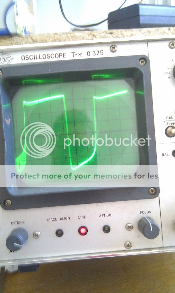
Here are scope shots at different gain levels. And I get that nasty sharp edge which is probably the problem.
Signal is taken directly after the second stage(before tonestack).
Input signal : Sine wave 1 kHz aprox 0.5V - 1V pp amplitude.
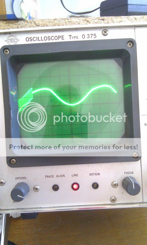
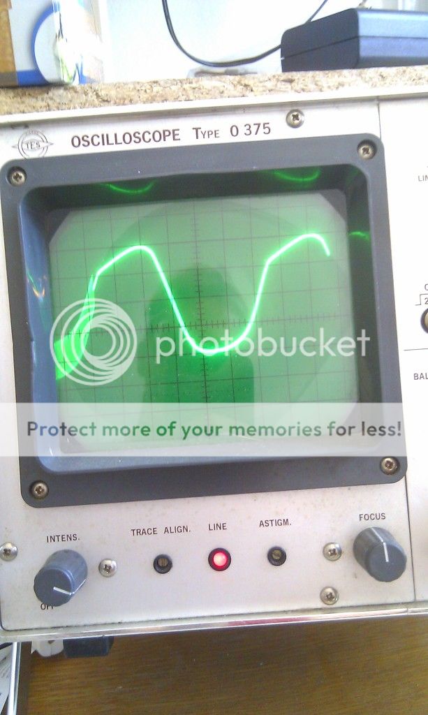
After first stage it is still nice sine wave, but amplified of course, after second stage I get this:
50% gain

75% gain
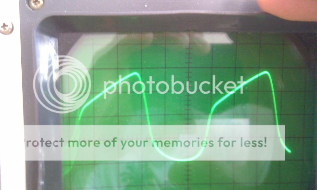
100% gain

Notice the difference in duty cycle (no longer equal time length of top and bottom part of the signal).
My interpretation is that the bottom half is grid current limiting, the top is cut-off? But it should be flat top not at an angle?
Schematic is standard
200V B+, 100k plate resistors, 2k7 first stage bias resistor + 1u5 cap, 1k5 bias resistor at second stage + 2u cap.
I tried biased it differently(220k plate resistors and swapping bias resistors in all combinations) but picture was not much different.
I would like to get nice bluesy/early rock sounds but it is not like this now.
Could anybody figure out what is causing this slope with a sharp edge?
Here are scope shots at different gain levels. And I get that nasty sharp edge which is probably the problem.
Signal is taken directly after the second stage(before tonestack).
Input signal : Sine wave 1 kHz aprox 0.5V - 1V pp amplitude.
After first stage it is still nice sine wave, but amplified of course, after second stage I get this:
50% gain
75% gain
100% gain
Notice the difference in duty cycle (no longer equal time length of top and bottom part of the signal).
My interpretation is that the bottom half is grid current limiting, the top is cut-off? But it should be flat top not at an angle?
Schematic is standard
200V B+, 100k plate resistors, 2k7 first stage bias resistor + 1u5 cap, 1k5 bias resistor at second stage + 2u cap.
I tried biased it differently(220k plate resistors and swapping bias resistors in all combinations) but picture was not much different.
I would like to get nice bluesy/early rock sounds but it is not like this now.
Could anybody figure out what is causing this slope with a sharp edge?
Last edited:
A 50% duty cycle sounds hollow. That's why opamp based preamps can sound bad.
A tube won't make anything like a square wave with those small caps across the cathode resistors, but you should expect the leading edge to spike up. Try changing the frequency to see what happends. Disconnect the tone stack. It doesn't load a preamp tube equaly at all frequencies especially when the "Slope" resistor (normally 100K) is low.
What are the DC plate voltages? Your B+ is pretty low. Typical is more like 300V, maybe 250 for a bluesey muted tone.
B+ is 200V, thats all my tranny can supply.
Stages are connected like this:
end of stage 1 - 22n cap - 500k gain potentiometer - input of stage 2
I tried at all audible frequencies but the picture stayed the same.
Then I tried to disconnect the tone stack(Marshall style tone stack). replace dit with 22n cap for coupling
Now it looks like this: (excuse my dying scope)
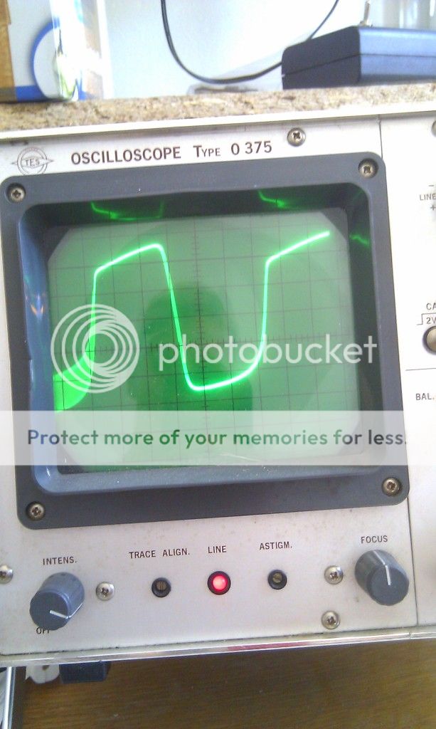
It stays almost the same in all frequencies.
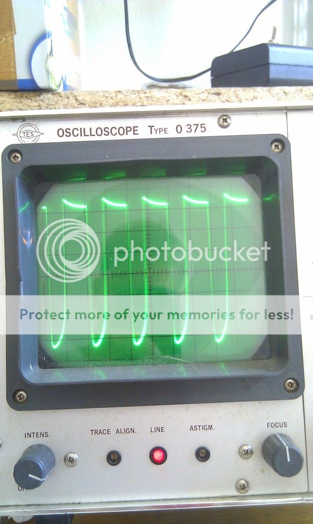
I wonder if it is normal to have that difference with a tonestack?
It actually sounds better without tone stack.
Stages are connected like this:
end of stage 1 - 22n cap - 500k gain potentiometer - input of stage 2
I tried at all audible frequencies but the picture stayed the same.
Then I tried to disconnect the tone stack(Marshall style tone stack). replace dit with 22n cap for coupling
Now it looks like this: (excuse my dying scope)
It stays almost the same in all frequencies.
I wonder if it is normal to have that difference with a tonestack?
It actually sounds better without tone stack.
Nasty flat peak, not tubelike at all. Tubes with too much gain that clip are supposed to make a nice rounded peak, whereas zener diodes and op amps used for clipping distortion ("2nd harmonic") chop the top off the waveform with a nasty flat edge that sounds bad. That inclined top might be power supply weakness. How old are your B+ electrolytic caps? Is there a cathode bias electrolytic cap that is weak?
Provide a schematic for more detailed response. Shouldn't be too hard to draw out, use word or powerpoint if you can't make a free schematic package work. But yes, all my 12AX7 tube stages use 275 VDC or above.
Provide a schematic for more detailed response. Shouldn't be too hard to draw out, use word or powerpoint if you can't make a free schematic package work. But yes, all my 12AX7 tube stages use 275 VDC or above.
Last edited:
Here is the schematic.
Note that all that scope shots were sourced before the PI.
Power supply section is identical to this one(including transformer). I scoped and measured the power supply and it is nice, doesn't collapse or has any ripple
http://diyguitarfreak.files.wordpress.com/2010/09/miniamp2-schematic1.jpg
Note that all that scope shots were sourced before the PI.
Power supply section is identical to this one(including transformer). I scoped and measured the power supply and it is nice, doesn't collapse or has any ripple
http://diyguitarfreak.files.wordpress.com/2010/09/miniamp2-schematic1.jpg
Attachments
Last edited:
I wonder if it is normal to have that difference with a tonestack?
The tone stack puts quite a load on the stage driving it. It's basically R18 at mid and high frequencies in the schematic you linked. In the Fender blackface amps R18 would be 100K. That's about as low as you can go when driving from the plate of a tube with 100K plate resistor. In the 5F6A and Marshall amps it's lower, but they drive the tone stack from a cathode follower. The cathode follower helps retain the highs but you need to boost the highs at the volume control or by smallish cathode bypass caps.
You didn't post the DC plate voltages but I expect they are higher than optimum. Looking at the plate curves of a 12AX7 I would say change the cathode resistors to 1.2K or 1.3K when the plate resistor is 100K and 3K if the plate resistor is 220K.
Sorry I cannot scope the input signal also because second channel on my scope doesn't work. But is nice sine wave from signal generator. I measured 0.33V rms which is like normal guitar humbucker output, it stays nice sine wave after first gain stage, after the second stage it becomes like on the pictures.
My amp schematic is the one I attached as amp.pdf
That scope shots I took are taken after the second stage right between 22n cap and 500k gain2 potentiometer.
I just don't know why clipping is so sharp-edged.
My amp schematic is the one I attached as amp.pdf
That scope shots I took are taken after the second stage right between 22n cap and 500k gain2 potentiometer.
I just don't know why clipping is so sharp-edged.
Sorry, I was looking at the MiniAmp 2.0 schematic.I am puzzled! Is this a brand name amp or a DIY ? No doubt you have tried another 12 AX7 tube?Still think 0.33V input is 10 times too high, but if waveform is clean after the first stage, it suggests a fault in stage 2. What is the volts/div on the vertical axis of your waveforms? It is impossible to tell what P-P voltage swing you are getting.
If you are doing what you say you are doing (0.33V rms input) then you are grossly overloading the second stage. A typical ECC83 stage can only accept an input voltage of up to about 1V rms, but you may be putting as much as 10-15V into it. The result is that it is swinging between grid current and grid cutoff, so the interstage coupling cap will have a shift of voltage and so the 2nd stage will have a shift of bias. This is complicated by the tiny cathode decoupling capacitor, so instead of something approaching a square wave you get a sloping top.
If you say its sounding harsh, you may want to look at the frequency shaping a bit more instead of the waveform. theres plently of bass cut, but not too much treble cut, put a low pass filter in by a 22pF cap from V1b grid to ground. that should round off those peaks a bit more too. Or, you could put a 22-47pF cap accross the plates of the PI.
Thanks guys for great responses. You really know your stuff.
Today I was overhauling that amp whole day.
First I used shielded cables for signal path. Then I put another gain potentiometer(before phase inverter). Because I noticed that the phase inverter started to distort before preamp. Now I can adjust level of preamp distortion and PI distortion.
I corrected bias on power tube.
I also put in new tone stack (Baxandall 2 band + mid boost switch).
And oh my god now that amp sounds so heavenly! Oh my god I have never played an amp that sounded so good with guitar plugged in directly, without any other effects.
Thanks guys. What a great forum!
http://www.duncanamps.com/technical/tonestack.html
http://www.duncanamps.com/technical/tonestack.html
Hi Guys
Are we assuming a Fender-style preamp, as there is no schematic posted?
The standard test signal for a guitar amp input is 70mVrms at 400Hz. Through a standard Fender preamp with a gain stage, EQ, volume and second stage, the output of the second stage can be made to distort mildly. This represents an 80Vrms signal!
The traditional flaw is the lack of grid-stops right at the tubes and one at all for the second stage.
Have fun
Kevin O'Connor
- Status
- This old topic is closed. If you want to reopen this topic, contact a moderator using the "Report Post" button.
- Home
- Live Sound
- Instruments and Amps
- How is tube distortion supposed to look like on a scope?