It is supposed for the guitar amp.
Schematic:
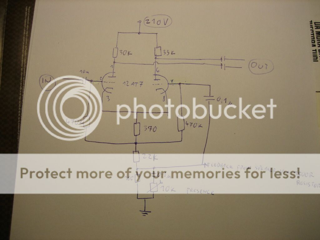
Output goes to ECC99 output tube.
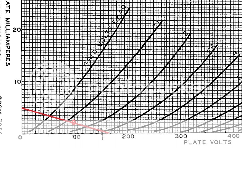
I was aiming on 2mA current and 45V across Tail resistor while having B+ voltage of 210V.
Load line of 33k is like this(with the circle of the desired idle bias)
Feedback from speaker isn't connected for now.
The problem is:
Across 33k plate resistor I get 75V drop, across the other one (30k) I get 10V!! I tried 2 different tubes and I also soldered 2 different resistors but no luck.
Power amp works great, preamp also. I had Cathodyne PI (which I didn't like) in before and I decided to make it LTP at the expense of 1 gain stage.
Amp works quiet and pops and makes weird noises when at full volume(which is very quiet compared to before )
Did I design PI correctly? What could be wrong?
Thanks.
Schematic:
Output goes to ECC99 output tube.
I was aiming on 2mA current and 45V across Tail resistor while having B+ voltage of 210V.
Load line of 33k is like this(with the circle of the desired idle bias)
Feedback from speaker isn't connected for now.
The problem is:
Across 33k plate resistor I get 75V drop, across the other one (30k) I get 10V!! I tried 2 different tubes and I also soldered 2 different resistors but no luck.
Power amp works great, preamp also. I had Cathodyne PI (which I didn't like) in before and I decided to make it LTP at the expense of 1 gain stage.
Amp works quiet and pops and makes weird noises when at full volume(which is very quiet compared to before )
Did I design PI correctly? What could be wrong?
Thanks.
Last edited:
Thanks guys.
Problem was that I had tonestack before PI and I forgot to wire that 10n cap, so one grid was pulled down.
I also changed that 22k resistor to 12k and it works great now. It is pretty well symmetrical clipping now.
But I still need to figure why Presence control does nothing and if I wire feedback from 8 ohm speaker tap it also makes no sonic difference.
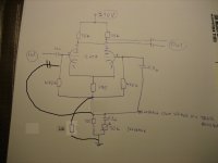
I've had very consistant results with one of marshalls presence circuits. Works perfect every time and allows some variation on your part if you like. Your presence "tail" in your drawing looks to have a 700ohm resistor I think this is the issue with your presense not working, increase that to 4.7 k, Then if your feedback comes from your 16ohm tap use 27k, 8ohm tap use 47k , 4 ohm use 100k. and put a 25k linear pot if youve got one handy, but 10 k will work too. Here it is in wired in one of my amps. Ax7 ay7, and at7 tubes all work fine in here - this will give you a very pronounced high roll off and it is tried and tested.
Sorry for my bad english but I didn't quite understand how should this be wired.
Thanks.
like this, maybe

Attachments

Hi Ramble
Your schematic is missing a connection at the top of the 10k.
Later splitters with 12AT7 have 47k plate loads, but the T works better than an X in either circuit providing the most clean output.
The original quiescent point selected by Jule is way too low. You have to acommodate the internal plate resistance which effectively reduces the potential signal swing. The tube cannot pull its plate all the way down to its cathode, like a BJT or mosfet can for their respective high-current paths, so the idle voltage has to be set to about two-thirds B+ for a symmetric output. This can be adjust by tweaking the cathode bias resistor.
Have fun
Kevin O'Connor
- Status
- This old topic is closed. If you want to reopen this topic, contact a moderator using the "Report Post" button.
- Home
- Live Sound
- Instruments and Amps
- Designed 12AT7 Long Tail Pair phase inverter - half of it doesn't work right